
Method of instrumenting a component

a technology of component and instrumentation, applied in the field of monitoring operating environment, can solve the problems of critical component failure, turbine vanes, blades and other components tend to vibrate during operation, and design and operator deficient information regarding the operational relationship of certain engine components

Inactive Publication Date: 2009-08-11
SIEMENS ENERGY INC
View PDF53 Cites 29 Cited by
  • Summary
  • Abstract
  • Description
  • Claims
  • Application Information

AI Technical Summary

Problems solved by technology

Despite the extreme sophistication of gas turbine engines, such as turbines for generating electrical power or aircraft engines for commercial and military use, designers and operators have deficient information with respect to the operational relationship of certain engine components.
This is due at least in part to harsh operating conditions and close tolerances between certain components, which often prevent using traditional sensors for collecting accurate information of critical engine components.
Nonetheless, turbine vanes, blades and other components tend to vibrate during operation due to air flowing through the turbine.
This flow induced vibration leads to wear at contact surfaces causing inefficient turbine operation and may lead to critical component failure.

Method used


Image

  • Method of instrumenting a component
  • Method of instrumenting a component
  • Method of instrumenting a component

Examples


Embodiment Construction

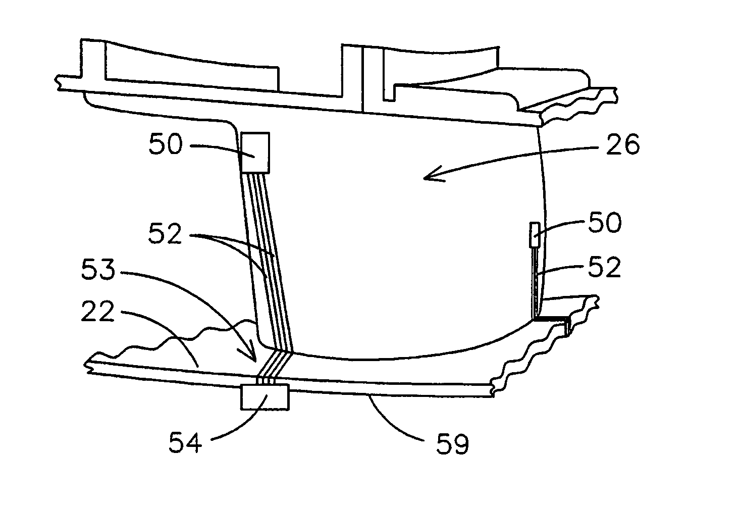
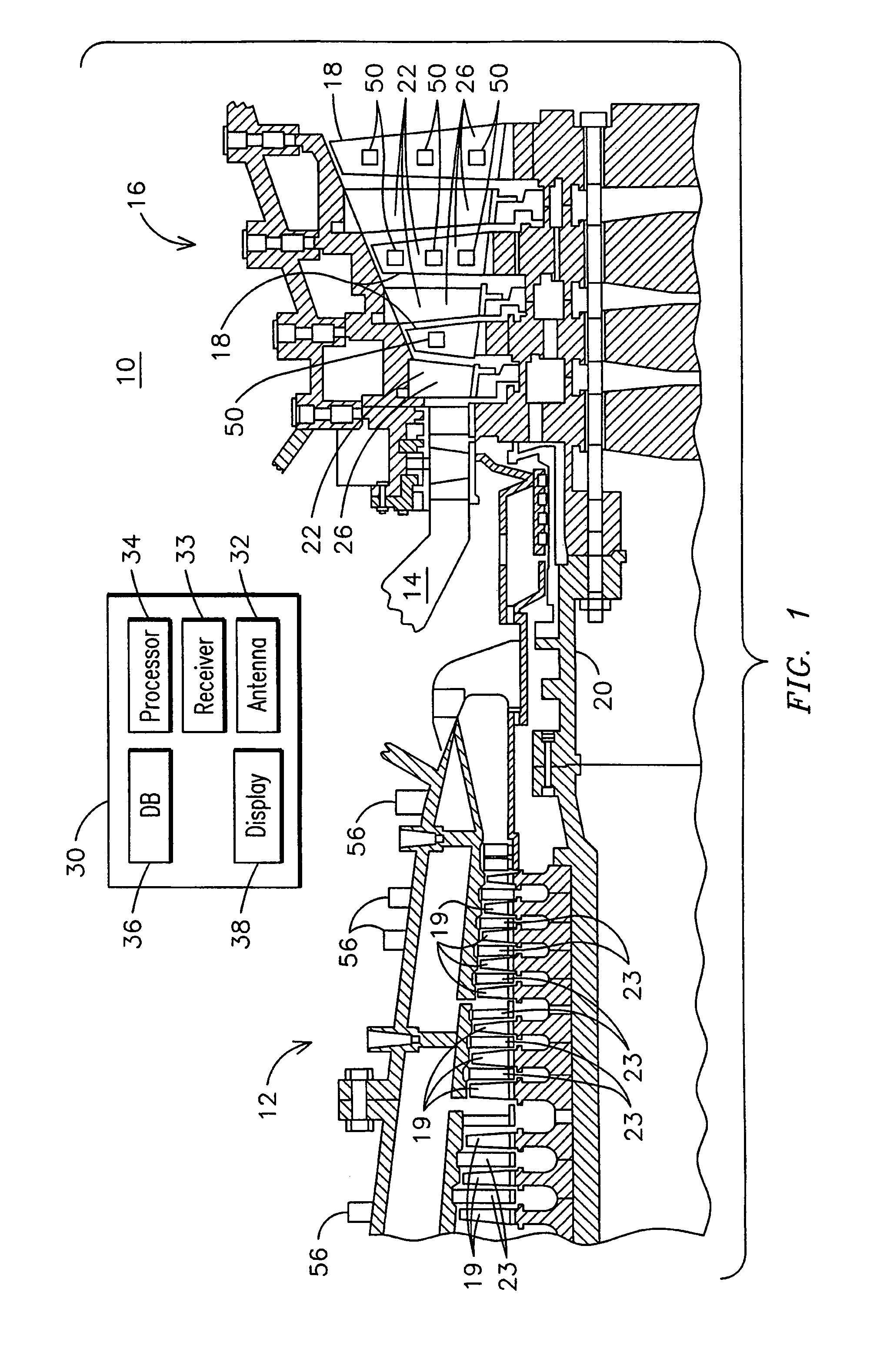
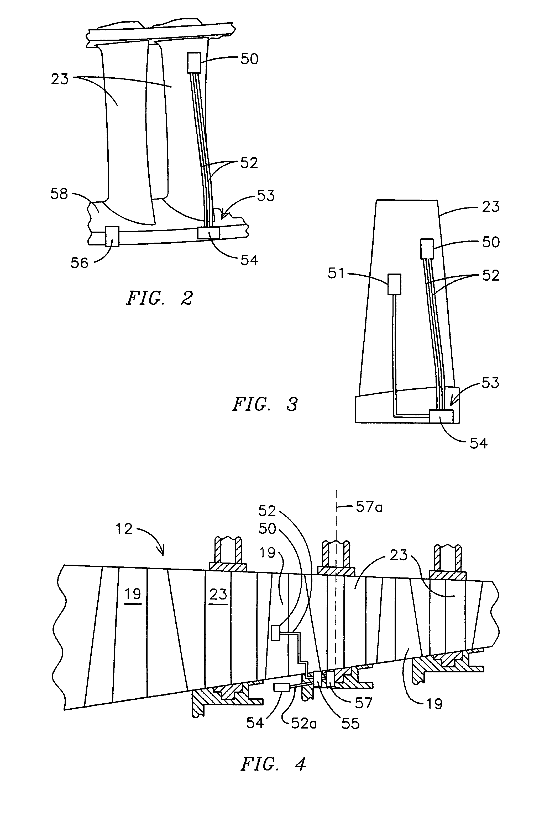
[0023]FIG. 1 illustrates an exemplary combustion turbine 10 such as a gas turbine used for generating electricity as will be recognized by those skilled in the art. Embodiments of the invention may be used with combustion turbine 10 or in numerous other operating environments. For example, embodiments may be used in aircraft engines for evaluating operation parameters and relationships of vibrating component.

[0024]Combustion turbine 10 may include a compressor 12, at least one combustor 14 (broken away) and a turbine 16. Compressor 12, combustor 14 and turbine 16 are sometimes referred to collectively as a gas turbine engine. Turbine 16 includes a plurality of rotating blades 18, secured to a rotatable central shaft 20. A plurality of stationary vanes 22 are positioned between blades 18, with vanes 22 being dimensioned and configured to guide air over blades 18. Blades 18 and vanes 22 will typically be made from nickel-cobalt, and may be coated with a thermal barrier coating 26, suc...


PUM

PropertyMeasurementUnit
operating temperaturesaaaaaaaaaa
thicknessaaaaaaaaaa

Abstract

A method of instrumenting a first component (210) for use in a combustion turbine engine (10) wherein the first component (210) has a surface contacted by a second component during operation of the combustion turbine engine (10). The method may include depositing an insulating layer (260) on the surface of the first component (210) and depositing a first conductive lead (232, 254) on the insulating layer (260). A piezoelectric material (230) may be deposited in electrical communication with the first conductive lead (232, 254) and a second conductive lead (236, 256) may be deposited in electrical communication with the piezoelectric material (230) and be insulated from the first conductive lead (232, 254) to form a sensor (50) for detecting pressure exerted on the surface of the first component (210) during operation of the combustion turbine engine (10).

Description

CROSS REFERENCE TO RELATED APPLICATIONS[0001]This application is a continuation-in-part of pending application Ser. No. 11 / 122,566 filed May 5, 2005, which is a continuation-in-part of application Ser. No. 11 / 018,816 filed Dec. 20, 2004 now U.S. Pat. No. 7,270,890, which claims the benefit of U.S. Provisional Patent Application No. 60 / 581,662 filed Jun. 21, 2004 and is a continuation-in-part of application Ser. No. 10 / 252,236 filed Sep. 23, 2002, U.S. Pat. No. 6,838,157, all of which are specifically incorporated herein by reference.FIELD OF THE INVENTION[0002]The present invention relates generally to monitoring operating environments and in particular to embedded sensors for sensing operating parameters of components within an operating environment such as a gas turbine engine.BACKGROUND OF THE INVENTION[0003]Despite the extreme sophistication of gas turbine engines, such as turbines for generating electrical power or aircraft engines for commercial and military use, designers and...

Claims


Application Information

Patent Timeline
Patent Type & Authority Patents(United States)
IPC IPC(8): B32B15/04C23C4/00B32B9/04F01D17/02F01D17/08F01D21/00
CPCF01D17/02F01D17/08F01D17/085F01D21/003G01P15/0915G01H1/006Y10T428/26F05D2230/90F05D2260/80F05D2230/30B33Y80/00Y10T428/8305
Inventor SABOL, STEPHEN M.SUBRAMANIAN, RAMESH
Owner SIEMENS ENERGY INC
Learn More