Optical absorption spectrometer and method for measuring concentration of a substance
- Summary
- Abstract
- Description
- Claims
- Application Information
AI Technical Summary
Benefits of technology
Problems solved by technology
Method used
Image
Examples
first embodiment
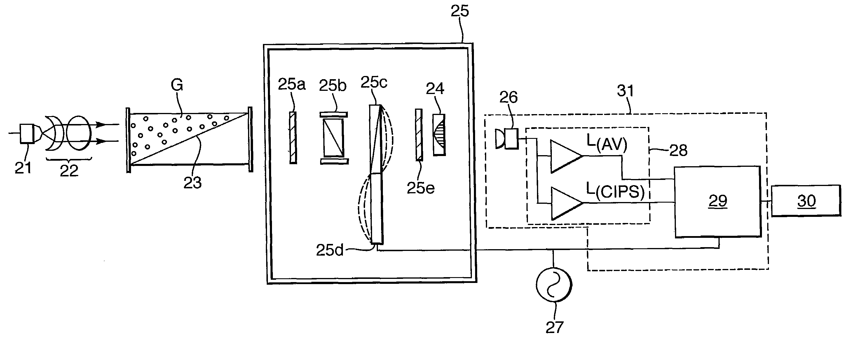
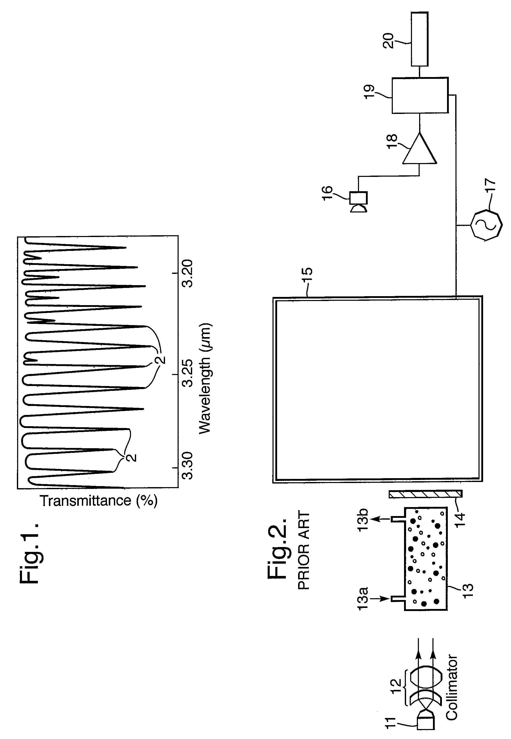
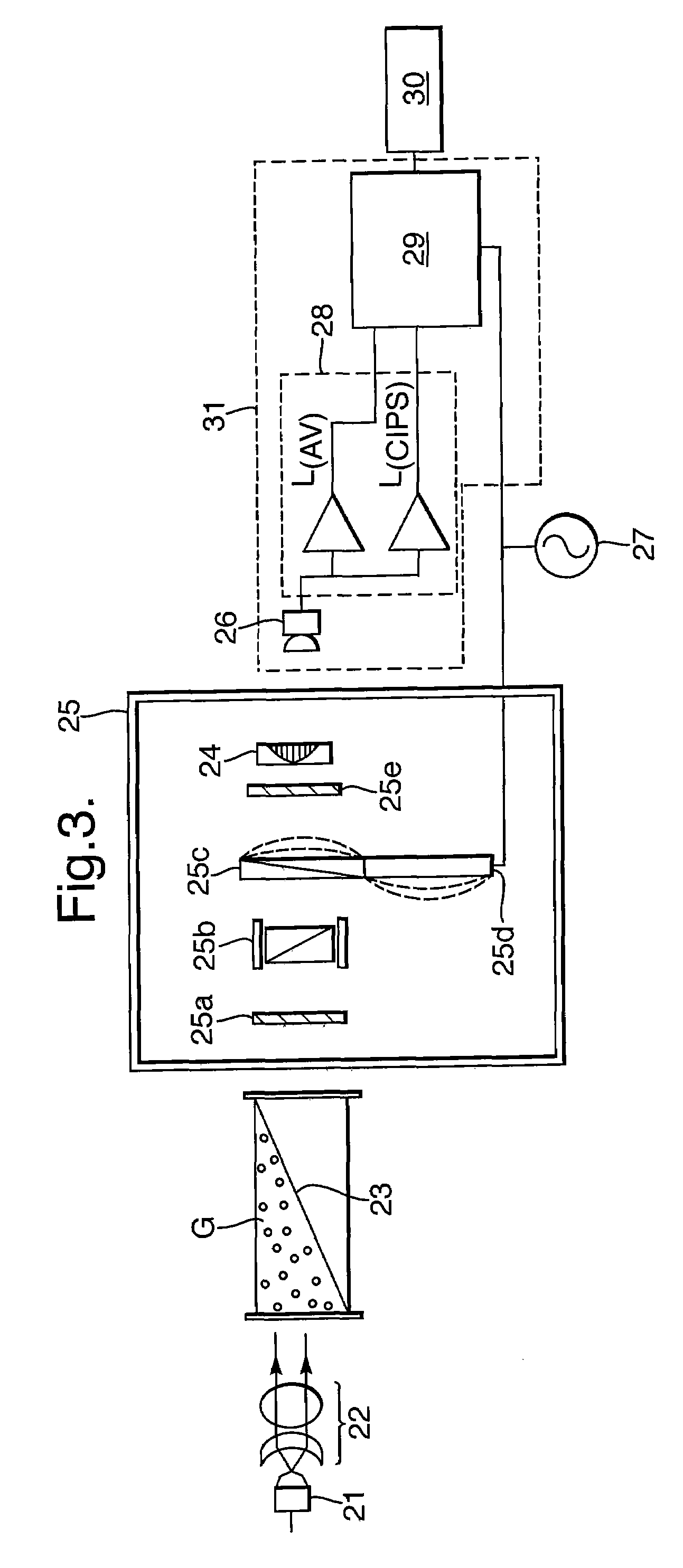
[0086]FIG. 3 shows the present invention, which is a CIPS having a modified gas cavity 23. The remaining components shown in FIG. 3 largely correspond to the FIG. 2 example.
[0087]A radiation source 21 such as a lamp, LED or laser, generates a radiation beam which is collimated by collimator 22 to pass through cavity 23 containing gas G which is the sample to be measured. Radiation transmitted by the gas G passes to the controlled interference polarization filter (cIPF) section 25. Here, the cIPF is shown to comprise two polariser elements 25a and 25e either side of an etalon 25b and a crystal 25c which exhibits induced birefringence. The birefringence is induced by a piezoelectric driver 25d supplied from an AC voltage 27 and synchronised with the processor 29.
[0088]In this example, the last component of cIPF 25 is a bandpass filter 24 which corresponds in function to filter 14 shown in FIG. 2.
[0089]Radiation transmitted by the cIPF 25 is detected by detector assembly 31 which compr...
second embodiment
[0091]A simpler example of a suitable gas cavity used in the invention is shown in FIG. 4. Here, the cavity 32 is defined between walls 33a and 33b of a chamber which comprises means for varying the cavity dimensions in the form of a partition 34 dividing off a volume containing radiation-transparent material T. The walls 33a and 33b and the partition 34 are all substantially transparent to the radiation, at least in the vicinity of the radiation beam(s) passing therethrough. The radiation transparent material T may be a solid material (e.g. it could be a continuation of the wall 33B or the partition 34), or it could be an inert gas such as nitrogen, i.e. one which does not absorb the radiation. The presence of volume T effectively causes the cavity dimension parallel to the radiation beam to vary along a perpendicular direction in a stepwise manner.
[0092]For clarity, FIG. 4 does not show the surrounding components of the spectrometer (which could be a CIPS or NDIR spectrometer, for...
third embodiment
[0097]FIG. 5 shows another cavity for use in an absorption spectrometer. As in the embodiment of FIG. 3, here the cavity 40 has a triangular cross-section.
[0098]The cavity 40 is defined within a chamber having walls 41a and b and a partition 42 creating a sample-free volume of radiation transparent material T. As in the example of FIG. 4, any radiation transparent material could be used, but nitrogen is particularly preferred. The partition 40 could be fixed or could be movable by a user such that the dimensions of the cavity 40 could be adjusted according to the measurement conditions.
[0099]As in FIG. 4, the three radiation rays AA′, BB′ and CC′ are depicted. In this example, each of the paths traverses a different distance through the sample gas G since the dimension of the gas cavity 40 varies continuously from top to bottom. In this case, the variation is linear whereas in other cases any other function e.g. curved, sinusoidal or parabolic could be used instead.
[0100]Again, this...
PUM
 Abstract
Description
Claims
Application Information
 - R&D
- Intellectual Property
- Life Sciences
- Materials
- Tech Scout
- Unparalleled Data Quality
- Higher Quality Content
- 60% Fewer Hallucinations
Browse by: Latest US Patents, China's latest patents, Technical Efficacy Thesaurus, Application Domain, Technology Topic, Popular Technical Reports.
© 2025 PatSnap. All rights reserved.Legal|Privacy policy|Modern Slavery Act Transparency Statement|Sitemap|About US| Contact US: help@patsnap.com


