Method for producing multiple magnetic layers of materials with known thickness and composition using a one-step electrodeposition process

Inactive Publication Date: 2009-08-04
IBM CORP
View PDF16 Cites 12 Cited by
  • Summary
  • Abstract
  • Description
  • Claims
  • Application Information

AI Technical Summary

Benefits of technology

[0017]A write head having multi-layer pole tips is also provided. The write head includes a first pole tip and a second pole tip opposing the first pole tip. A write gap is defined between the first and second pole tips. A conductive coil is built in between the first and the second pole tip. Preferably, the first and second pole tips each have two layers of dif

Problems solved by technology

One drawback of this approach is that the second layer is formed by dissolution and not deposition.
This is significantly more difficult to control in terms of thickness and composition, because the amount and the relative frequency of dissolution is dictated by the inherent kinetics and not as much by the current.
Also disadvantageous, the second layer (layer 7 in the disclosure) has to be significantly thinner than the first layer because of the above mentioned problem of thickness control, which gets worse as the dissolution duration increases.
However, using this direct current method, the composition range that can be achieved is very limited.

Method used


Image

  • Method for producing multiple magnetic layers of materials with known thickness and composition using a one-step electrodeposition process
  • Method for producing multiple magnetic layers of materials with known thickness and composition using a one-step electrodeposition process
  • Method for producing multiple magnetic layers of materials with known thickness and composition using a one-step electrodeposition process

Examples


Embodiment Construction

[0028]The following description is the best embodiment presently contemplated for carrying out the present invention. This description is made for the purpose of illustrating the general principles of the present invention and is not meant to limit the inventive concepts claimed herein.

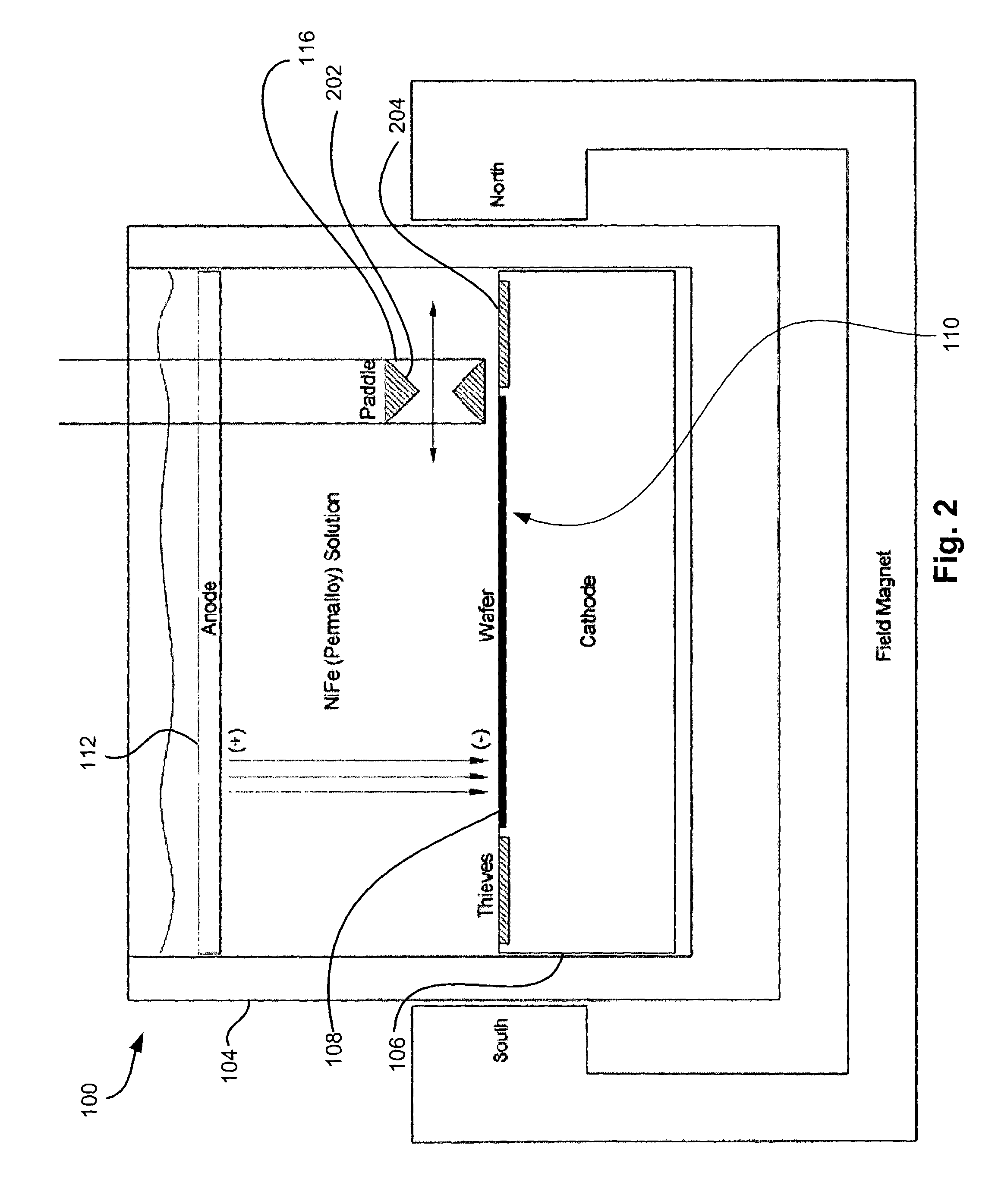
[0029]FIG. 1 depicts a plating cell 100 having a paddle assembly 102. The plating of nickel-iron alloys is performed in a container 104. The walls of the container 104 can be composed of a dielectric material such as glass or a plastic such as polymethacrylate. Positioned in the container 104 is a cathode 106. The cathode 106 may be composed of a metal plate having plater's tape composed of an insoluble polymer adhesively secured to the exterior thereof on the edges and lower surface to protect it from the electroplating bath and thus giving a very ill defined current density and current density distribution. A substrate 108 to be plated is positioned in a depression 110 (FIG. 2) in the cathode 106. N...


PUM


Abstract

A method for multi-layer electrodeposition in a single bath is also provided. A substrate is immersed in a bath. An electrodeposition operation is initiated for depositing a first layer of material on the substrate. The electrodeposition operation includes agitating the bath and applying current pulses. The electrodeposition operation is later altered for depositing a second layer of material on the first layer, where the second layer is of a different composition than the first layer. In the altered mode, the current density is changed for altering a composition of material deposited on the substrate, the duration and / or frequency of the current pulses are altered, and the bath is agitated at a different rate of agitation.

Description

FIELD OF THE INVENTION[0001]The present invention relates to electrodeposition, and more particularly, this invention relates to creating multiple layers of varying compositions from a single plating bath.BACKGROUND OF THE INVENTION[0002]Electroplating is a common process for depositing a thin film of metal or alloy on a workpiece article such as various electronic components for example. In electroplating, the article is placed in a suitable electrolyte bath containing ions of a metal to be deposited. The article forms a cathode, which is connected to the negative terminal of a power supply, and a suitable anode is connected to the positive terminal of the power supply. Electrical current flows between the anode and cathode through the electrolyte, and metal is deposited on the article by an electrochemical reaction.[0003]Electroplating is widely used in the thin film head industry to fabricate magnetic and non-magnetic materials that constitute the writing part of a read-write hea...

Claims


Application Information

Patent Timeline
IPC IPC(8): C25D5/10C25D21/10C25D5/18C25D5/14G11B5/31G11B5/39
CPCC25D5/14C25D5/18G11B5/3156G11B5/3163G11B5/313G11B5/3967
Inventor HIXON-GOLDSMITH, APRIL DAWNLAST, MATTHEW WALTERRAMASUBRAMANIAN, MURALISCHAEFER, ROLF BEATUS
Owner IBM CORP
Why Eureka
Try Eureka