
Phase-locked loop filter capacitance with a drag current

a phase-locked loop and capacitance technology, applied in pulse automatic control, electric devices, etc., can solve the problems of increasing the overall size of the pll, increasing the noise contribution, increasing the difficulty of implementation, etc., and achieves the effect of reducing the loop bandwidth, increasing the capacitor area, and being easy to manag

Inactive Publication Date: 2009-07-28
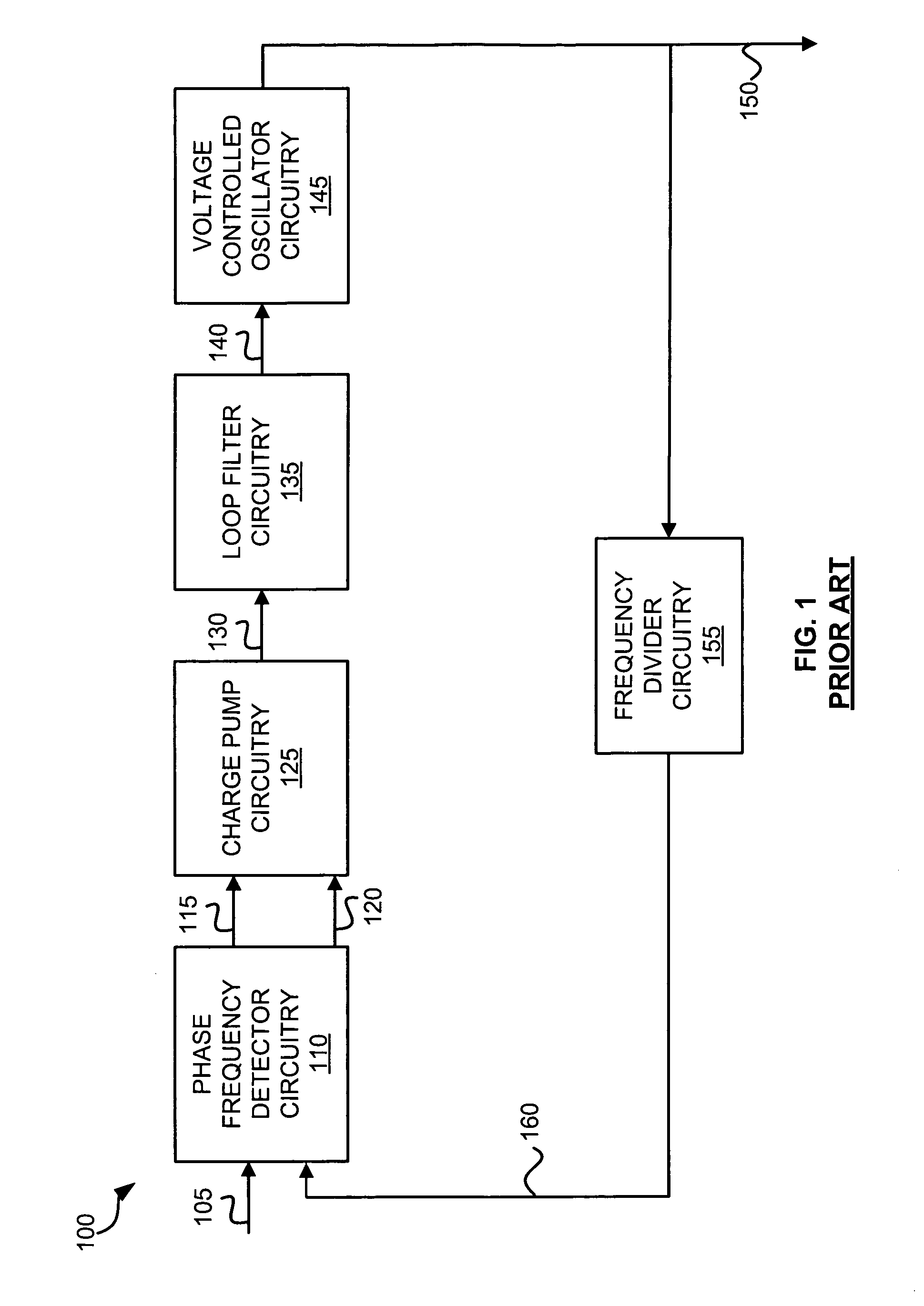
CONVERSANT INTPROP MANAGEMENT INC
View PDF54 Cites 2 Cited by
  • Summary
  • Abstract
  • Description
  • Claims
  • Application Information

AI Technical Summary

Benefits of technology

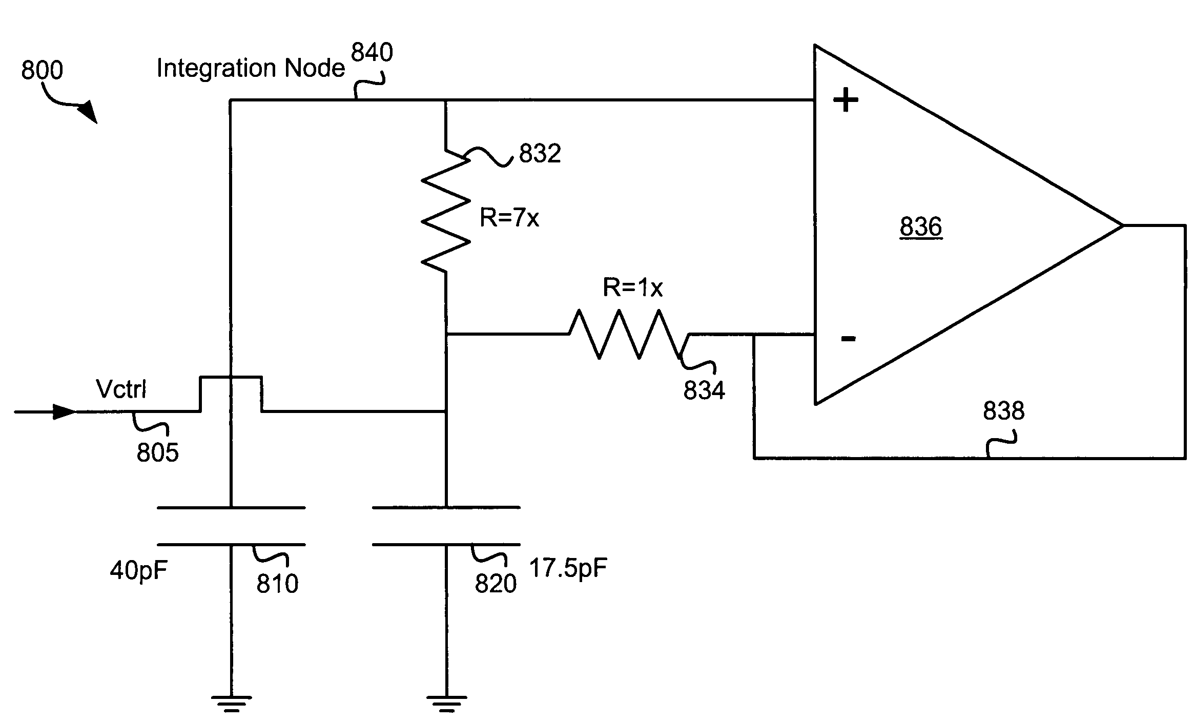
"The invention provides a phase-locked loop circuitry with drag current circuitry to address issues in conventional PLL circuits. The drag current circuitry allows for lowering the loop bandwidth without affecting the charge pump current or increasing capacitor area. It also improves power supply noise rejection and enables faster locking behavior."

Problems solved by technology

However, decreasing the charge pump current increases its noise contribution and becomes increasingly difficult to implement at low levels.
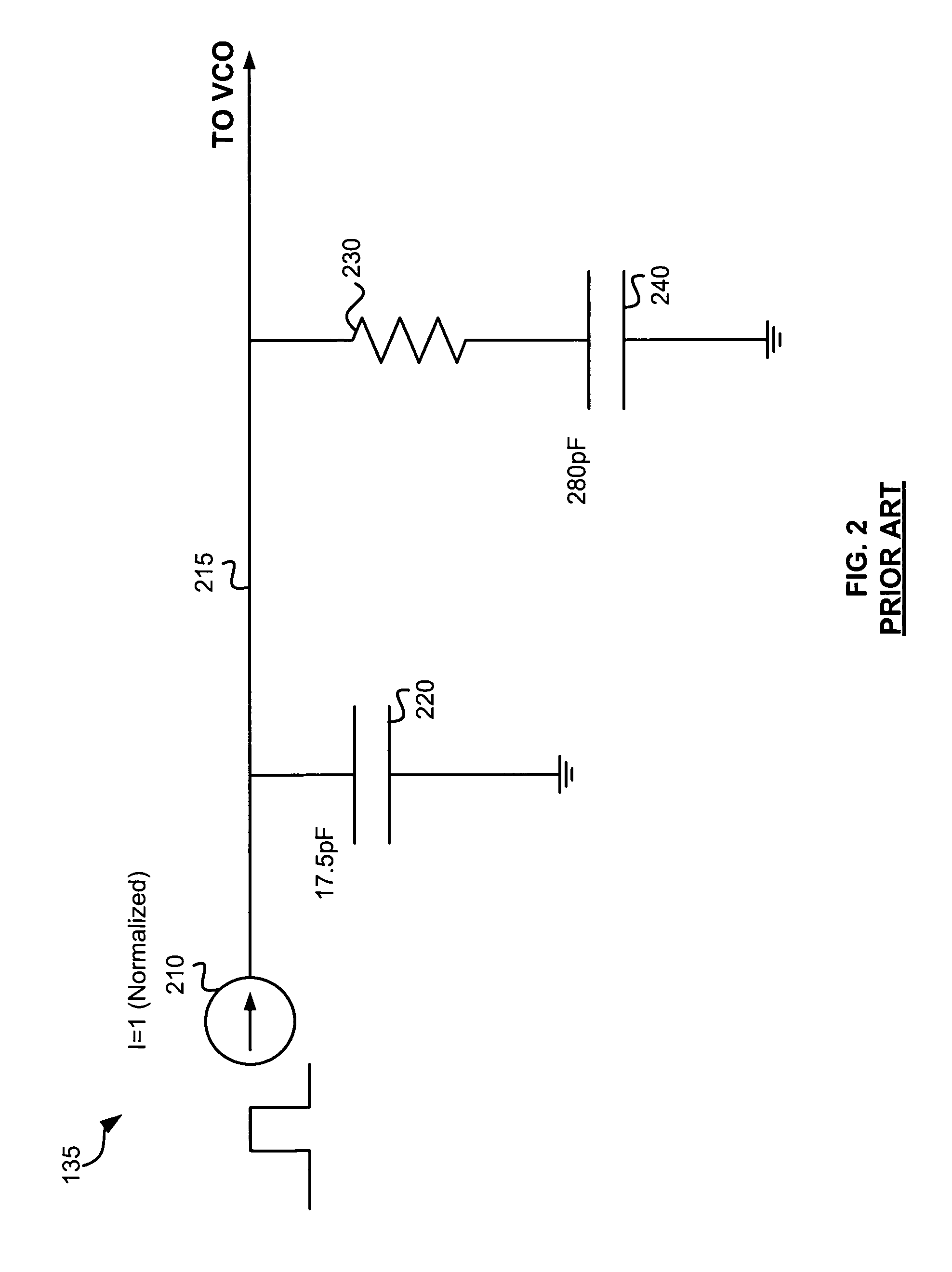
Consequently, one limitation is the overall size of the PLL increases because of the increased size of the capacitor.

Method used


Image

  • Phase-locked loop filter capacitance with a drag current
  • Phase-locked loop filter capacitance with a drag current
  • Phase-locked loop filter capacitance with a drag current

Examples


Embodiment Construction

[0024]The embodiments discussed herein are illustrative of examples of the present invention. As these embodiments of the present invention are described with reference to illustrations, various modifications or adaptations of the methods and / or specific structures described may become apparent to those skilled in the art. All such modifications, adaptations, or variations that rely upon the teachings of the present invention, and through which these teachings have advanced the art, are considered to be within the scope of the present invention. Hence, these descriptions and drawings should not be considered in a limiting sense, as it is understood that the present invention is in no way limited to only the embodiments illustrated.

[0025]The embodiments discussed herein are described in the context of phase-locked loop circuitry. However, other embodiments of the invention may be implemented in any circuit that implements “an integration function”, which can reduce the size of the in...


PUM


Abstract

Phase-locked loop circuitry includes charge pump circuitry, loop filter circuitry, and drag current circuitry. The charge pump circuitry generates a charge pump current based on a phase of an input signal. The loop filter circuitry receives the charge pump current. The drag current circuitry generates a drag current to draw charge in the opposite direction from the charging current from a loop filter integration capacitor in the loop filter circuitry that does not include voltage sensing circuitry.

Description

BACKGROUND[0001]1. Technical Field[0002]The present invention relates generally to phase-locked loop circuitry and more particularly to phase-locked loop filter capacitance with a drag current.[0003]2. Description of Related Art[0004]Filter circuitry may contain capacitors to filter certain frequencies of a signal. Filter circuitry is used in numerous types of electronic circuits. One type of electronic circuit is a phase-locked loop. A phase-locked loop (PLL) is an electronic circuit with a voltage- or current-driven oscillator that is adjusted to match in phase (and thus lock on) the frequency of an input signal. In addition, PLLs are used to generate a signal, modulate or demodulate a signal, reconstitute a signal with less noise, and multiply or divide a frequency. Examples of applications for PLLs include frequency synthesizers for RF local oscillators or digital clock generation, recovery of small signals that otherwise would be lost in noise, lock-in amplifiers, and recovery ...

Claims


Application Information

Patent Timeline
Patent Type & Authority Patents(United States)
IPC IPC(8): H03L7/00
CPCH03L7/093H03L7/0891
Inventor CAPLAN, RANDY
Owner CONVERSANT INTPROP MANAGEMENT INC
Learn More