
Recording and reproducing device

a recording and reproducing device technology, applied in the direction of recording signal processing, instruments, color signal processing circuits, etc., can solve the problems of inability to accurately reproduce the entire document data, rapid change in light intensity, and inability to perform effective correction of defective pixels

Inactive Publication Date: 2009-07-21
FUJITSU LTD
View PDF5 Cites 4 Cited by
  • Summary
  • Abstract
  • Description
  • Claims
  • Application Information

AI Technical Summary

Benefits of technology

The present invention is a device that can record and play holographic data. It includes a section to shine reference light onto the recording medium to read the data, a section to generate information light based on the page data to be written, a section to shine the information light onto the same area as the reference light, a section to detect the light that comes back, a section to store known data, a section to examine any defects in the device, and a section to fix any defects. The technical effect of this invention is to provide a device that can accurately record and play holographic data with minimal defects.

Problems solved by technology

When recording information such as document data as the holographic data, the entire document data may not be reproduced if a defect is found in only one pixel.
Further, when the information is not an image, there may be a rapid change in the light intensity between adjacent pixels, and an effective correction may not be performed on the defective pixel.
However, in reality, when manufacturing a CCD having at least a few million pixels as used herein, it is difficult to constantly manufacture a non-defective CCD.
Further, a sophisticated manufacturing technique is necessary in manufacturing the non-defective CCD at good yield, leading to increase in cost.
As the number of pixels increase, the probability of manufacturing the defective CCD increases, thereby lowering the yield.

Method used


Image

  • Recording and reproducing device
  • Recording and reproducing device
  • Recording and reproducing device

Examples


first example

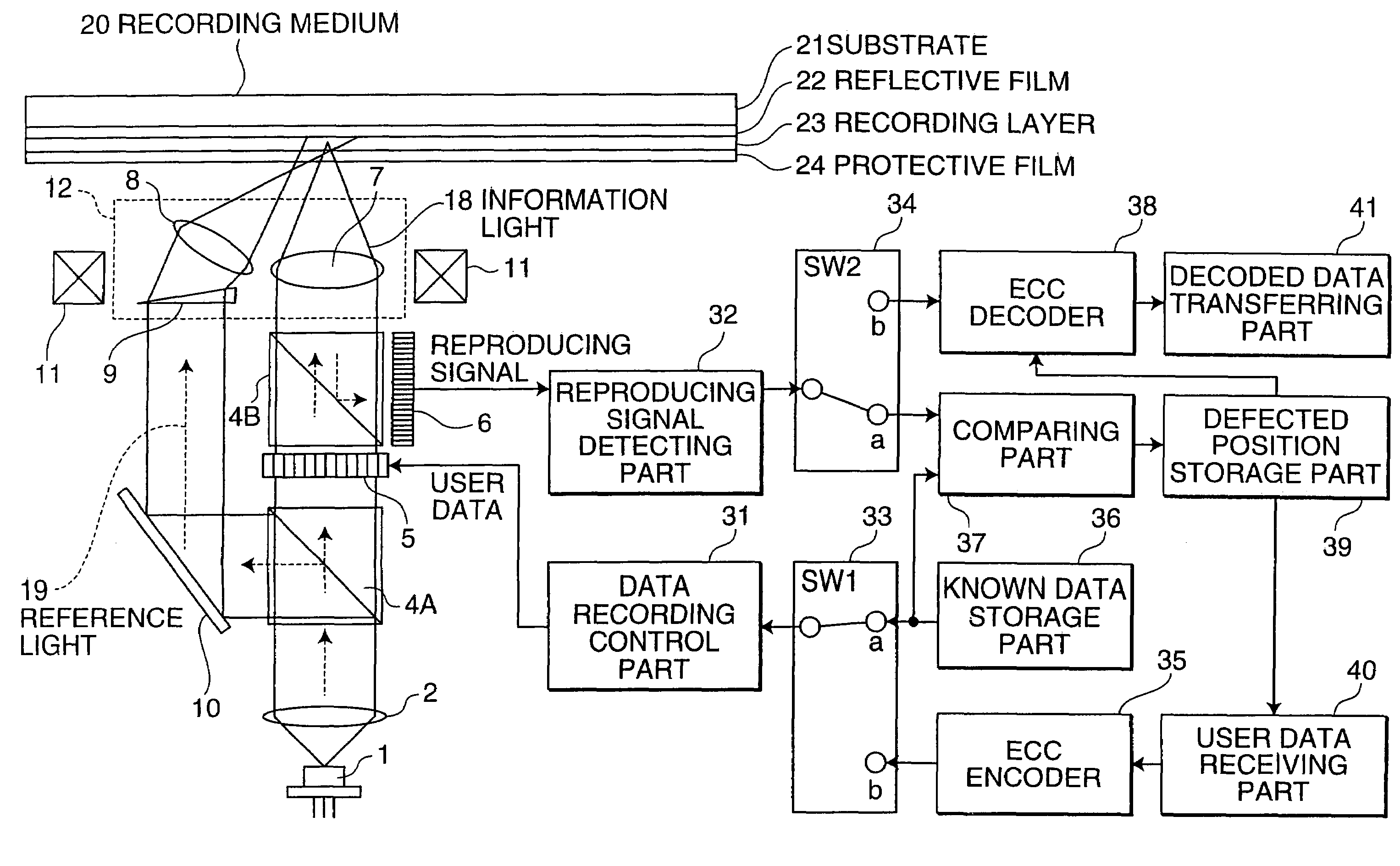
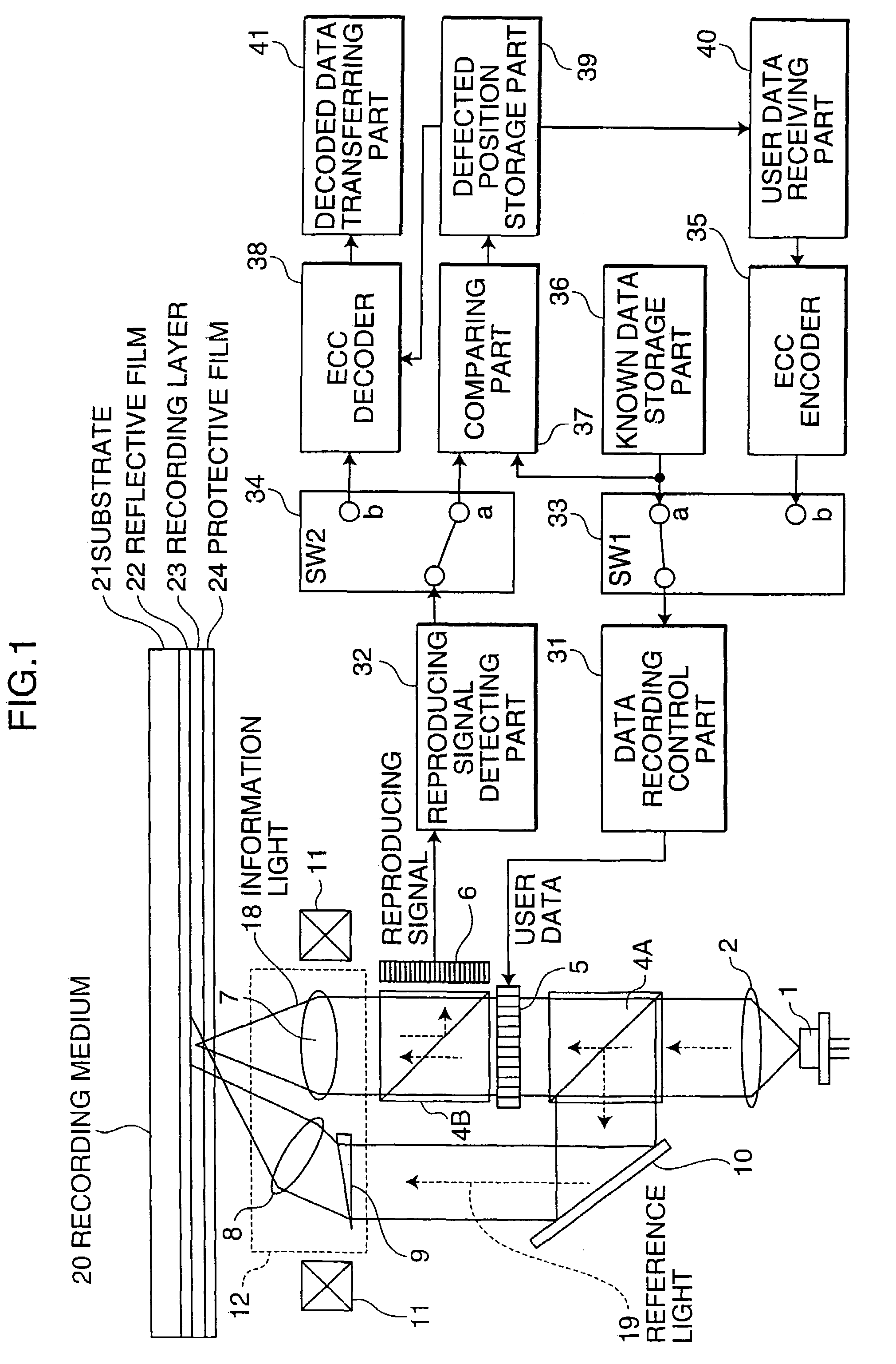
[0108]Herein, a case of examining the defective position of the CCD 6 and performing erase and correction of the pixel of the detected defective position will now be described.

[0109]The erase and correction is error correction using the supplied defective position information, with a pixel of the detected defective position as erased data.

[0110]In the first example, the defective position information acquired by the defect examination is supplied to the ECC decoder 38 to enhance the error correction capability of the ECC decoder and to properly restore and reproduce the data of the defective position.

[0111]Generally, in the error correcting process using the ECC, if the position of the pixel of the CCD where the error is produced, that is, the defective position is known, the error correction capability can be enhanced, and thus the defective position of the CCD is detected in advance to handle the data corresponding to the defective position as the erased data. The original data at...

second example

Data Recording Process in Second Example

[0168]FIG. 4 shows a flowchart for the data recording process of the second example of the present invention.

[0169]In step S31, the user data receiving section 40 receives the request for recording the user data transmitted from the personal computer and the like.

[0170]The request for recording includes information such as logic address to be written, the file name to be written and the user data content.

[0171]Next, in step S32, the switching section SW1 (33) is switched to logically connect the ECC encoder 35 and the data recording control section 31.

[0172]In step S33, the defective position information is read from the defective position storage section 39.

[0173]In step S34, using the read defective position information, the dummy data is inserted to the defective position and the recording data to be written to the medium is generated.

[0174]If, for example, a plurality of defective positions indicated by the defective position information e...

case b)

(Case B)

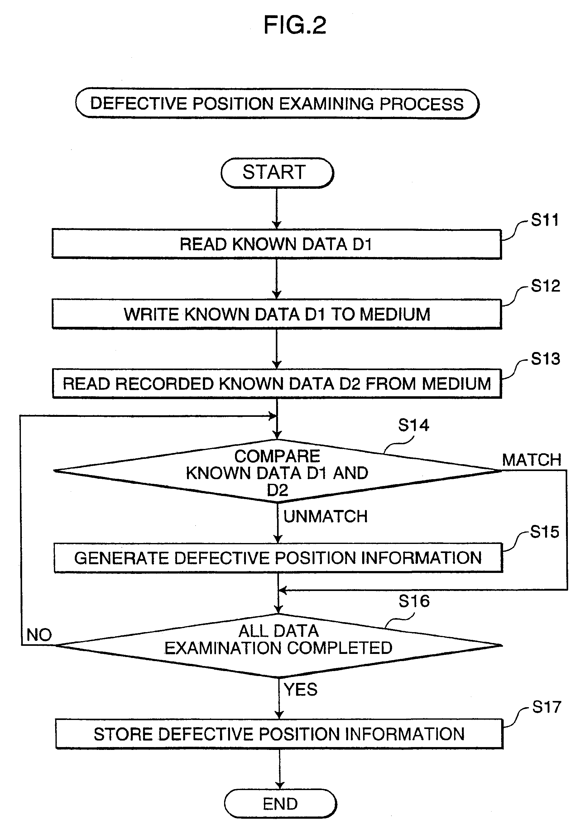
[0195](B1) When the known page data D3 in the known data storage section 36 of the device is recorded on the medium and the recorded known data D3′ is reproduced, unmatched data is not found and is normal.

[0196](B2) When the known page data D4 recorded on the medium in advance is reproduced, the defect is detected.

[0197]If both B1 and B2 are realized, the defect is not present in the CCD 6 and the SLM 5, but the defect is present in the known data recorded in the medium 20.


PUM

PropertyMeasurementUnit
timeaaaaaaaaaa
luminous fluxesaaaaaaaaaa
luminous fluxaaaaaaaaaa

Abstract

A recording and reproducing device includes: a reference light irradiating section; a spatial light modulating section for generating information light; an information light irradiating section for irradiating the same region as a region irradiated with the reference light, with the information light; a light detecting section for receiving reproduction light; a known data storage section; a defect examining section for examining a defective position of the spatial light modulating section or the light detecting section by irradiating the information light and the reference light to write the known page data to the holographic recording medium, and then irradiating the medium with the reference light to read the known page data written on the holographic recording medium from the reproduction light received by the light detecting section; and a reproducing control section for restoring and reproducing the original data of the defective position using information of the defective position detected by the defect examining section.

Description

CROSS-REFERENCE TO RELATED APPLICATION[0001]This application is related to Japanese patent application No. 2005-053929 filed on Feb. 28, 2005, whose priority is claimed under 35 USC §119, the disclosure of which is incorporated by reference in its entirety.BACKGROUND OF THE INVENTION[0002]1. Field of the Invention[0003]The present invention relates to recording and reproducing devices, in particular, a recording and reproducing device for recording holographic information with two luminous fluxes of reference light and information light, and for reproducing the holographic information using reference light.[0004]2. Description of the Related Art[0005]A holographic recording method is proposed as a method for multiplexedly recording information on the same position.[0006]Holographic recording is recording performed by separating a luminous flux from the same light source into reference light and information light; irradiating the same position on a recording medium with the reference...

Claims


Application Information

Patent Timeline
Patent Type & Authority Patents(United States)
IPC IPC(8): G11B7/00
CPCG11B7/0065G11B20/182H04N1/401G11B2220/2504G11B20/1833
Inventor TAGUCHI, MASAKAZU
Owner FUJITSU LTD
Learn More