Drum washing machine

a drum and washing machine technology, applied in the field of drum washing machines, can solve the problems of drum washing machine, transient vibration of the drum b>3, transient vibration problem raised, etc., and achieve the effect of reducing the vibration of the tub

Inactive Publication Date: 2009-07-21
LG ELECTRONICS INC
View PDF26 Cites 0 Cited by
  • Summary
  • Abstract
  • Description
  • Claims
  • Application Information

AI Technical Summary

Benefits of technology

[0018]An object of the present invention is to provide a drum washing machine in which vibrations of a cabinet, being generated as a tub vibrates, are minimized as a connection structure between a damper and the cabinet is improved.
[0020]To achieve these and other advantages and in accordance with the purpose of the present invention, as embodied and broadly described, a drum washing machine of the present invention includes a cabinet, a drum, a tub, a damper, and an elastic member. The drum is rotatably provided in the cabinet. The tub is provided in the cabinet for surrounding an outer surface of the drum. A damper is provided between the cabinet and the tub to reduce vibrations of the tub. The elastic member connects one end of the damper to the cabinet and elastically vibrates when the vibrations of the tub are delivered through the damper.

Problems solved by technology

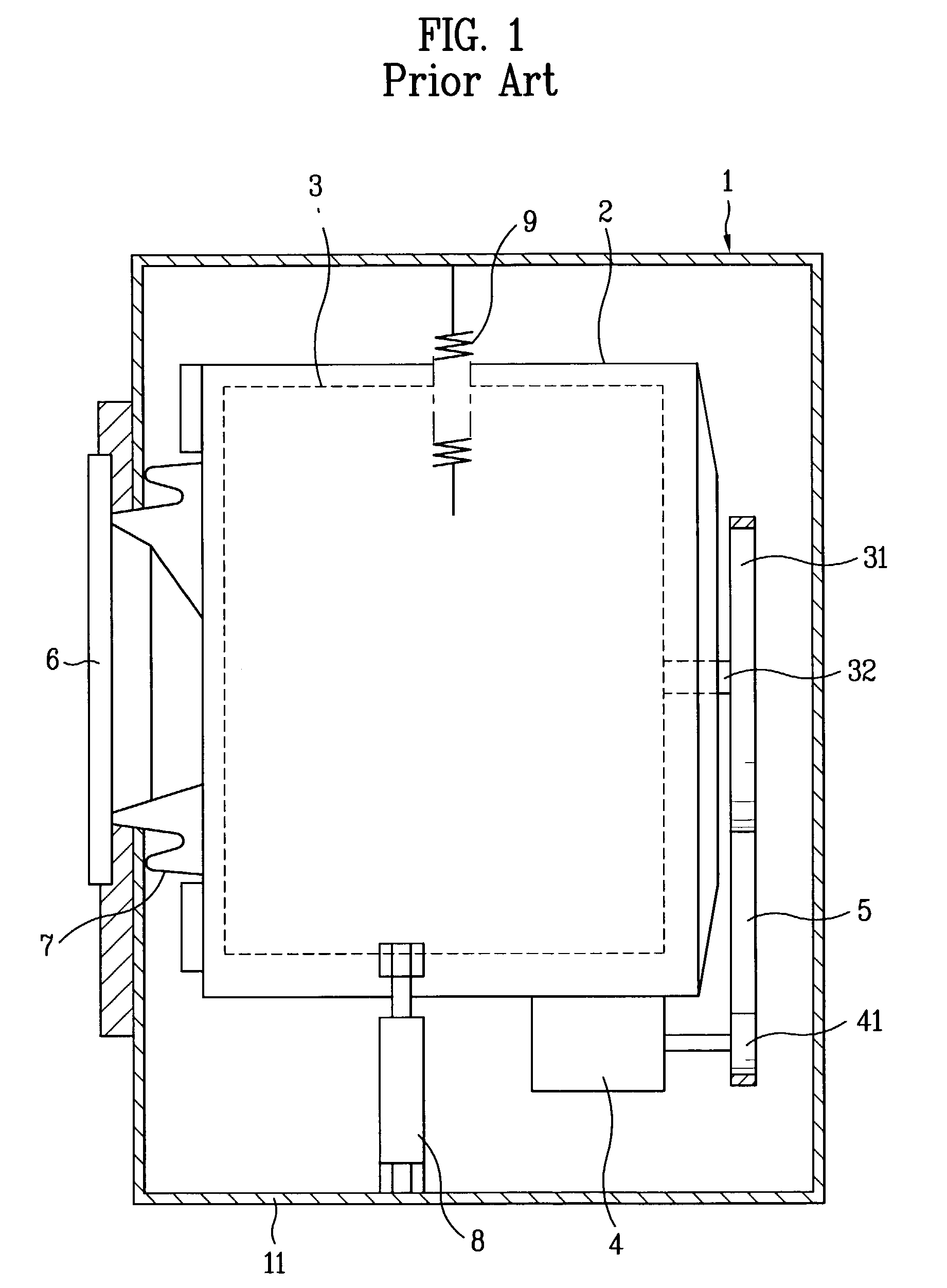
In the meantime, the most common problem of the drum washing machine is transient vibration of the drum 3.
On the contrary, if the damper is designed to be smaller, the vibration becomes smooth during the rated revolution for dewatering but the transient vibration problem is raised.
The transient vibration generates unpleasant noise and a disorder of component parts and thus, may reduce the lifetime of the washing machine.

Method used


Image

  • Drum washing machine
  • Drum washing machine
  • Drum washing machine

Examples


first embodiment

[0041]Referring to FIGS. 3A and 3B, an elastic member 102 is formed of a plate. Two brackets 103 projecting from central portions on the upper surface of the elastic member 102 are provided to face each other. One end of a damper 8 is inserted between the two brackets 103 and fastened by bolts 13 and nuts 14.

[0042]A groove 101 with predetermined depth is formed on a base surface 11 of the cabinet 1 and the elastic member 102 is formed over the groove 101 with its both ends put on the upper faces of the cabinet 1 as shown in FIG. 3.

[0043]At this time, a fixing member 104 is provided to fix each edge of the elastic member 102. A small-sized fixing groove 104a is formed on a lower part of the fixing member 104, so that one end of the elastic member 102 can be inserted thereto so to be supported. After one end of the elastic member 102 is inserted to the fixing groove 104a, the fixing member 104 is fixed onto the base face 11 of the cabinet 1. The fixing member 104 may be fixed by being...

second embodiment

[0047]Referring to FIGS. 4A and 4B, an elastic member 102 is formed of a plate. Two brackets 103 projecting from two different central portions of the upper surface of the elastic member 102 are formed to face each other. One end of a damper 8 is inserted between the two brackets 103 and fastened by bolts 13 and nuts 14.

[0048]A plurality of projections are formed in a cabinet 1. An elastic member 102 is placed on the projections with its both ends put on the upper faces of the projections.

[0049]At this time, a fixing member 102 may be further included to fix the ends of the elastic member onto the projections. A small-sized fixing groove 104a is formed on a lower part of the fixing member 104 so that one end of the elastic member 102 can be inserted thereto so to be supported. After one end of the elastic member 102 is inserted to the fixing groove 104a, the fixing member 104 is fixed onto the projections 107. The fixing member 104 may be fixed by being welded or by being fastened b...


PUM


Abstract

A drum washing machine is disclosed, in which a damper is not directly fixed to a cabinet but has an elastic member as an intermediate to be fixed to the cabinet. Accordingly, vibrations of the damper are absorbed to vibrations of the elastic member without being directly delivered to the cabinet and also, during transient vibration of the drum, the damper acts to attenuate the transient vibration as the amplitude of the elastic member is limited by the action of the upper and lower limiters.

Description

[0001]This application claims the benefit of the Korean Application No. P2002-47150 filed on Aug. 9, 2002, which is hereby incorporated by reference.BACKGROUND OF THE INVENTION[0002]1. Field of the Invention[0003]The present invention relates to a drum washing machine.[0004]2. Background of the Related Art[0005]A washing machine removes laundry dirt and stains using chemical decomposition and mechanical impact through washing, rinsing, and dewatering processes. Generally, there are three types of washing machines: a pulsator washing machine, an agitator washing machine, and a drum washing machine.[0006]Among them, the drum washing machine being provided with a drum having a plurality of projections performs a washing process by slowly and horizontally rotating the drum with a detergent, washing water, and a laundry object in it. In this way, in the drum washing machine, the washing process is performed by impact and frictional force being generated as the laundry is raised and dropp...

Claims


Application Information

Patent Timeline
Patent Type & Authority Patents(United States)
IPC IPC(8): D06F37/04D06F37/20D06F37/22
CPCD06F37/22D06F37/20F16F15/022D06F39/125Y02B40/00
Inventor CHANG, JAE WON
Owner LG ELECTRONICS INC
Why Eureka
Try Eureka