Step-and-shoot cardiac CT imaging

a ct imaging and step-and-shoot technology, applied in the field of step-and-shoot cardiac ct imaging, can solve the problems of organ failure, sudden death, organ failure,

Active Publication Date: 2009-07-07
GENERAL ELECTRIC CO
View PDF9 Cites 0 Cited by
  • Summary
  • Abstract
  • Description
  • Claims
  • Application Information

AI Technical Summary

Problems solved by technology

The narrowing or constriction of vessels carrying blood to the heart is a well-known cause of heart attacks and, gone untreated, can lead to sudden death.
In general, narrowing of blood carrying vessels supplying an organ will ultimately lead to compromised function of the organ in question, at best, and organ failure, at worst.
If the combination of gantry speed and helical pitch is not properly selected, the entire heart volume will not be uniformly covered in the reconstructed images.
Although small gaps could be filled by image space interpolation, larger gaps will lead to discontinuities and artifacts in the volume rendered images.
This is particularly problematic when considering the variation of heart rate in a typical patient.

Method used


Image

  • Step-and-shoot cardiac CT imaging
  • Step-and-shoot cardiac CT imaging
  • Step-and-shoot cardiac CT imaging

Examples


Embodiment Construction

[0027]In the following detailed description, reference is made to the accompanying drawings that form a part hereof, and in which is shown by way of illustration specific embodiments that may be practiced. These embodiments are described in sufficient detail to enable those skilled in the art to practice the embodiments, and it is to be understood that other embodiments may be utilized and that logical, mechanical, electrical and other changes may be made without departing from the scope of the embodiments. The following detailed description is, therefore, not to be taken as limiting the scope of the invention.

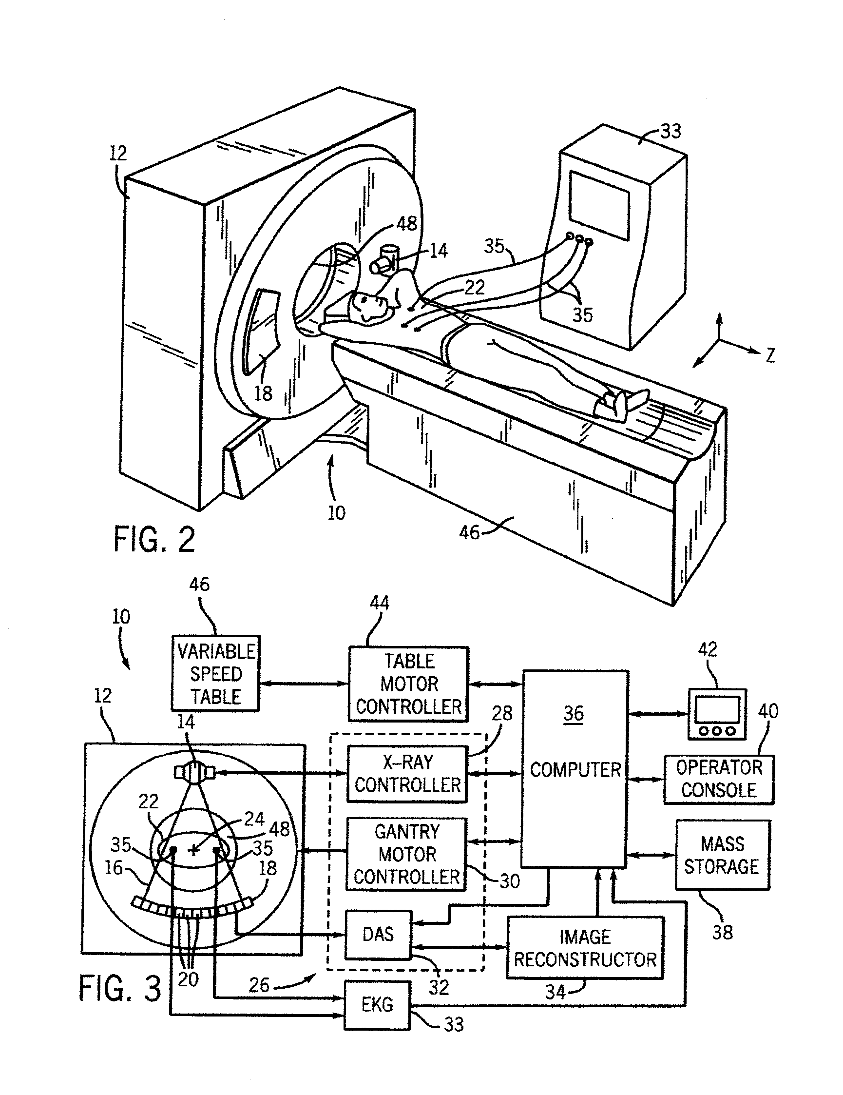
[0028]Referring to FIGS. 2 and 3, a computed tomography (CT) imaging system 10 is shown as including a gantry 12 having an x-ray source 14 that projects a beam of x-rays 16 toward a detector array 18 on the opposite side of the gantry 12. Detector array 18 is formed by a plurality of detectors 20 that together sense the projected x-rays that pass through a subject or patient 2...


PUM

PropertyMeasurementUnit
distanceaaaaaaaaaa
distanceaaaaaaaaaa
CT imagingaaaaaaaaaa

Abstract

A CT imaging system includes a gantry and a table in a movable relationship with the gantry. The CT imaging system also includes a controller configured to control relative movement between a subject disposed on the table and the gantry from a first data acquisition position to a second data acquisition position. The controller is also configured to determine a total scan time based on a first time for acquiring imaging data at the first data acquisition position and a second time for transitioning from the first data acquisition position to the second data acquisition position. The controller is also configured to disable data acquisition in an immediately subsequent cardiac cycle and re-enable data acquisition in the cardiac cycle following the immediately subsequent cardiac cycle if the total scan time exceeds one cardiac cycle of the subject. A method of CT imaging is also disclosed.

Description

CROSS REFERENCE TO RELATED APPLICATIONS[0001]This application is a continuation in part of U.S. patent application Ser. No. 11 / 160,028 filed Jun. 6, 2005. The application is incorporated herein by reference.BACKGROUND OF THE INVENTION[0002]The narrowing or constriction of vessels carrying blood to the heart is a well-known cause of heart attacks and, gone untreated, can lead to sudden death. In such stenotic vessels, it is known that the region immediately downstream from the constriction is characterized by having rapid flow velocities and / or complex flow patterns. In general, narrowing of blood carrying vessels supplying an organ will ultimately lead to compromised function of the organ in question, at best, and organ failure, at worst. Quantitative flow data can readily aid in the diagnosis and management of patients and also help in the basic understanding of disease processes. There are many techniques available for the measurement of blood flow, including imaging based methods...

Claims


Application Information

Patent Timeline
Patent Type & Authority Patents(United States)
IPC IPC(8): G01N23/083H05G1/62
CPCA61B5/0464A61B6/541A61B6/032A61B6/027A61B6/503A61B6/5264A61B6/527A61B5/363
Inventor HSIEH, JIANGLI, JIANYINGVASS, MELISSA L.TANG, XIANGYANGOKERLUND, DARIN ROBERTHOPPEL, BERNICE E.MOHR, KELLY ANNLONDT, JOHN HOWARD
Owner GENERAL ELECTRIC CO
Why Eureka
Try Eureka