Slow close valve

a technology of ball valve and handle, which is applied in the direction of valve details, valve housings, valve arrangements, etc., can solve the problems of difficult operation, wide known, and corrosion of ball valves made entirely of metallic components, and achieve the effect of facilitating remote operation of said handl

Active Publication Date: 2009-07-07
COLONIAL ENG
View PDF13 Cites 10 Cited by
  • Summary
  • Abstract
  • Description
  • Claims
  • Application Information

AI Technical Summary

Benefits of technology

[0007]The objects and purposes of the invention have been met by providing a valve which includes a tubular body having a bore flow passage, a valve element having a through flow passage, the valve element being supported in the through flow passage for rotation through a quarter turn about an axis transverse to the through flow passage. The through flow passage is aligned with the bore flow passage to permit flow when the valve element is positioned at a first end of the quarter turn and is misaligned with the bore flow passage to prevent flow when the valve element is at a second end of the quarter turn. An actuating valve stem and a manually engageable handle secured thereto are provided for selective slow operation of the actuating valve stem through a quarter-turn input motion for effecting opening or closing of the valve element to permit or prevent flow. A motion multiplication device is provided between the handle and the valve element and is operated by rotation of the handle. A tool engaging configuration is provided on the handle for facilitating a remote operation of the handle. The tool engaging configuration includes at least one upstanding embossment on an upwardly facing surface of the handle configured to engage with a tool to facilitate remote operation of said handle.

Problems solved by technology

It is widely known that ball valves made entirely of metallic components are subject to corrosion, especially when the valves are oriented in a buried application, usually in a hole provided in the earth's surface, which hole is then capped.
When the valves are made of metallic components, such as brass, they become corroded over time and difficult to operate, thereby necessitating replacement.

Method used


Image

  • Slow close valve
  • Slow close valve
  • Slow close valve

Examples


Embodiment Construction

[0014]Certain terminology will be used in the following description for convenience in reference only and will not be limiting. The words “up”, “down”, “right” and “left” will designate directions in the drawings to which reference is made. The words “in” and “out” will refer to directions toward and away from, respectively, the geometric center of the device and designated parts thereof. Such terminology will include derivatives and words of similar import.

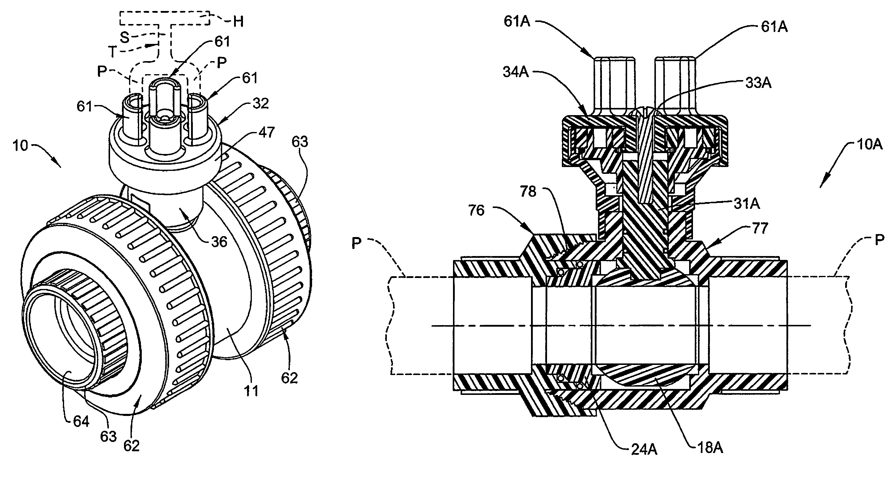
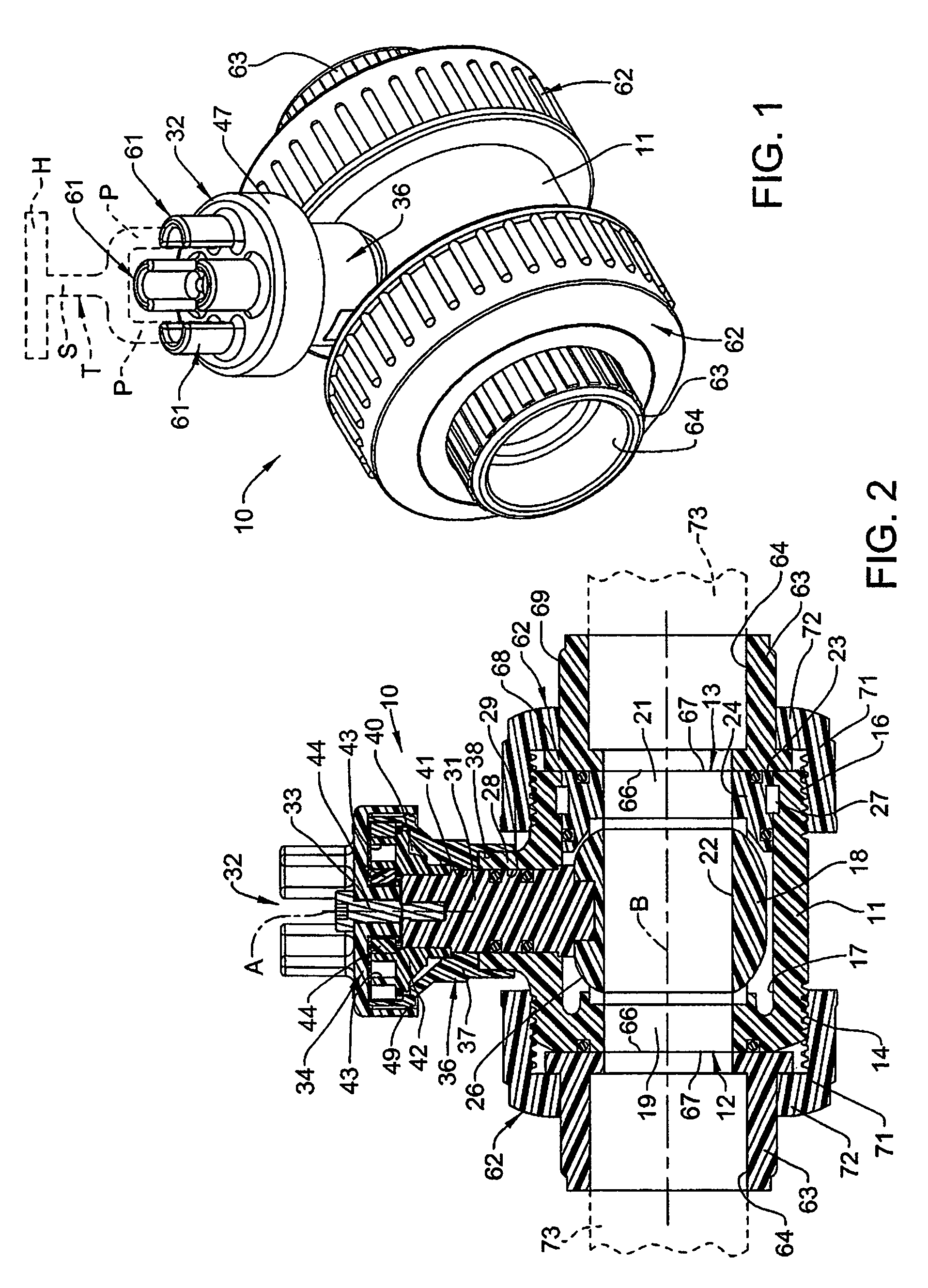
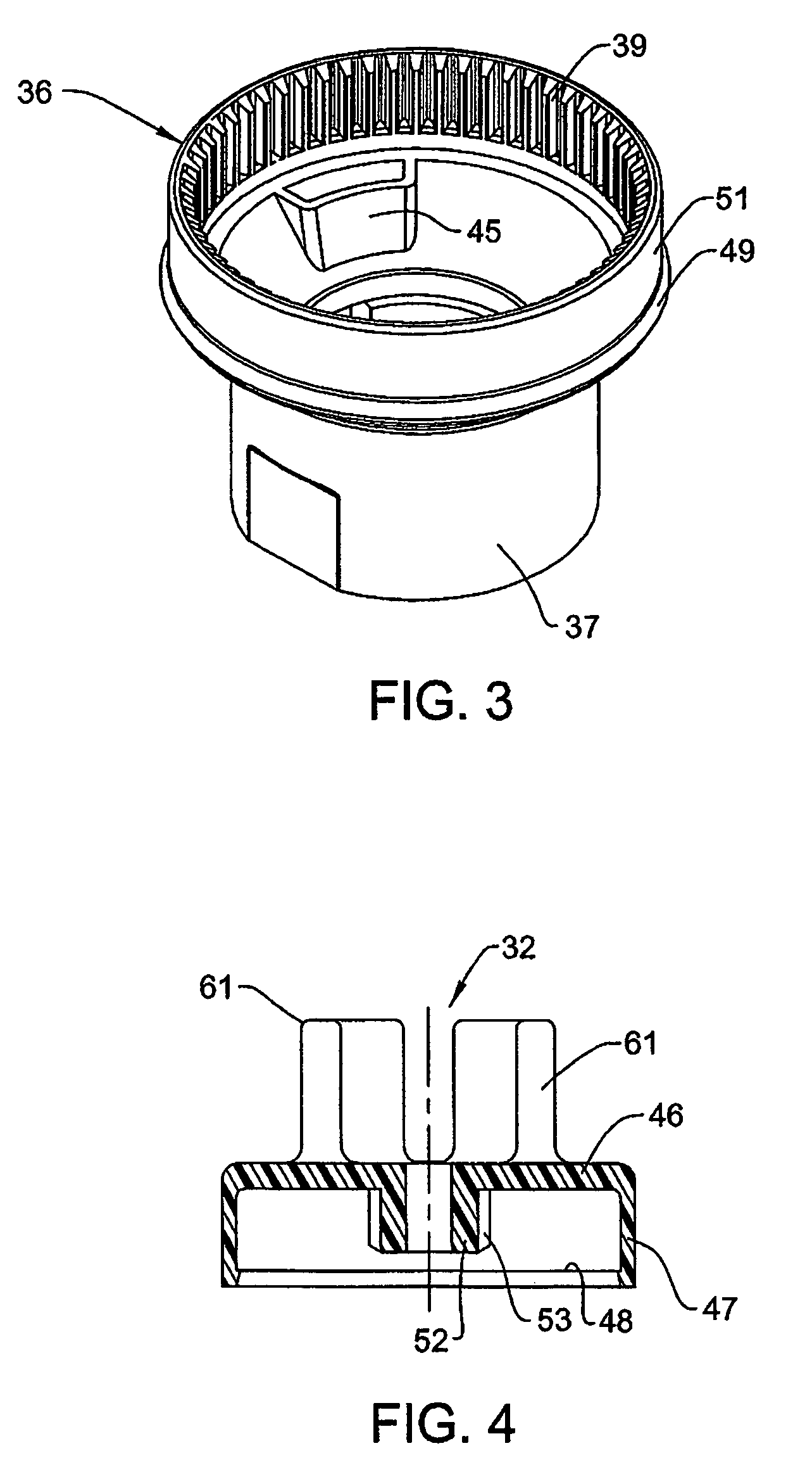
[0015]A first embodiment of a ball valve 10 embodying the invention is illustrated in FIGS. 1-4. A second embodiment of a ball valve 10A is illustrated in FIGS. 5-6.

[0016]Referring now to the first embodiment illustrated in FIGS. 1-4, the ball valve 10 includes a valve body 11 having an elongate cylindrical tubular configuration. Each end 12, 13 of the valve body has an external thread 14, 16, respectively, formed on the radially outwardly facing surface thereof. The hollow interior of the valve body 11 defines a chamber 17 where...


PUM


Abstract

A quarter turn valve includes a tubular body having a bore flow passage, a valve element having a through flow passage, the valve element being supported in the through flow passage for rotation about an axis transverse to the through flow passage. The through flow passage is aligned with the bore flow passage to permit flow when the valve element is positioned at a first end of the quarter turn and is misaligned with the bore flow passage to prevent flow when the valve element is at a second end of the quarter turn. A motion multiplication device is included for facilitating a slow operation of the valve element. A tool engaging configuration is provided on the handle for facilitating a remote operation of the handle.

Description

FIELD OF THE INVENTION[0001]This invention relates to an improvement in an all plastic ball valve having a feature facilitating operation thereof in a down-hole environment.BACKGROUND OF THE INVENTION[0002]Ball valves are well known in the field, including ball valves that are operated by a handle and the speed of movement of the valve element is determined by a motion multiplication means oriented between the handle and the valve element. U.S. Pat. Nos. 2,025,244 and 6,378,841 are just a few of the representative examples thereof.[0003]It is widely known that ball valves made entirely of metallic components are subject to corrosion, especially when the valves are oriented in a buried application, usually in a hole provided in the earth's surface, which hole is then capped. Access to a buried valve is gained by uncapping the hole and, in some situations, using a tool to facilitate operation thereof. When the valves are made of metallic components, such as brass, they become corroded...

Claims


Application Information

Patent Timeline
Patent Type & Authority Patents(United States)
IPC IPC(8): F16K31/44
CPCF16K5/0642F16K5/0652F16K31/535F16K31/46F16K27/067
Inventor BEEBE, PATRICK ALLEN
Owner COLONIAL ENG
Why Eureka
Try Eureka