
Spark ignition type internal combustion engine

a technology of internal combustion engine and spark ignition, which is applied in the direction of machines/engines, gaseous engine fuels, process and machine control, etc., can solve the problem of intensifying the knocking

Inactive Publication Date: 2009-07-07
NISSAN MOTOR CO LTD
View PDF9 Cites 35 Cited by
  • Summary
  • Abstract
  • Description
  • Claims
  • Application Information

AI Technical Summary

Benefits of technology

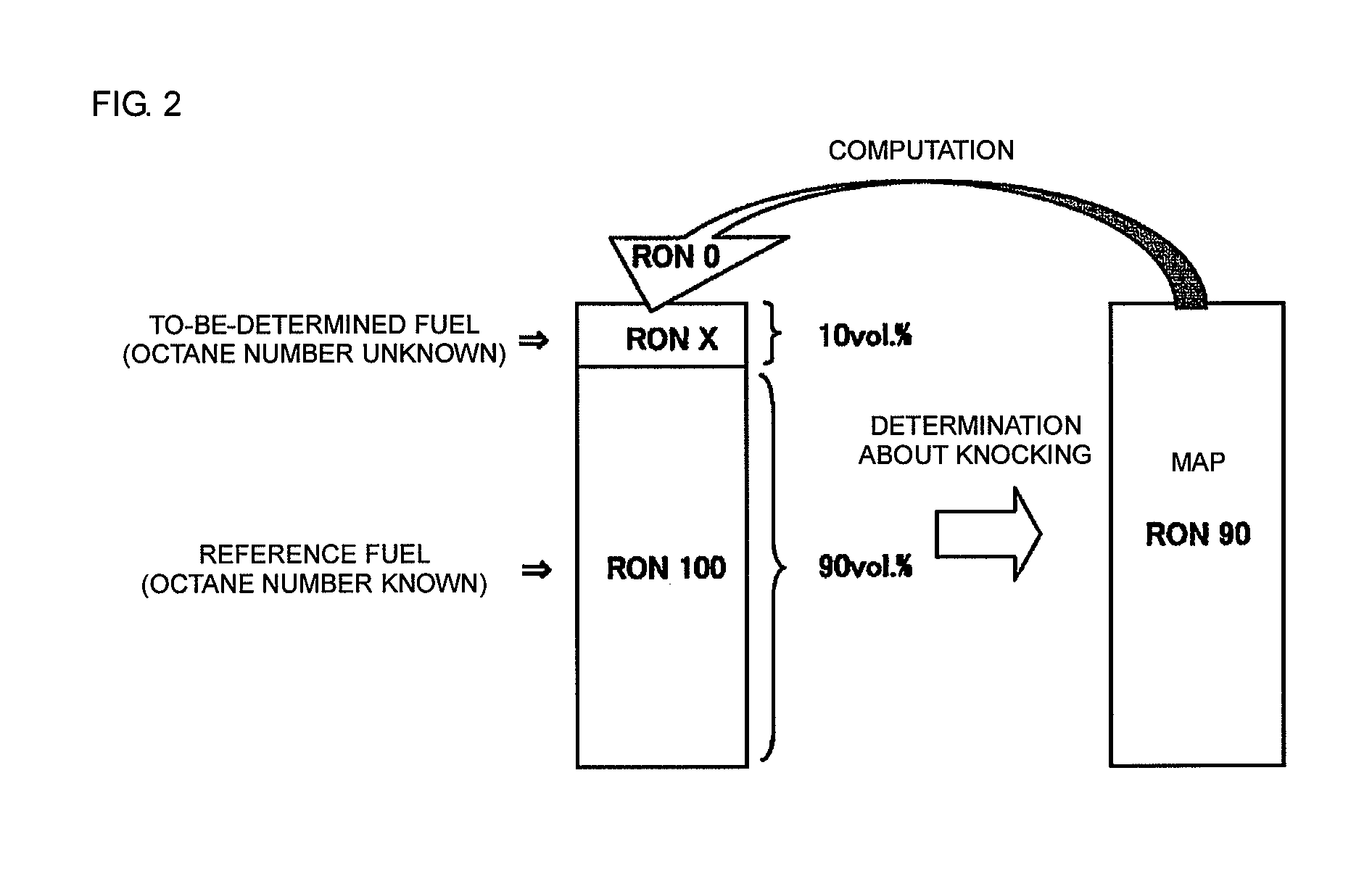
The present invention provides a spark-ignition type internal combustion engine that can easily determine the self-ignition property of a fuel. This is done by blending the fuel with a reference fuel and measuring the resulting self-ignition property of the blended fuel. The engine can then use this information to determine the unknown self-ignition property of the fuel. This method is simple and does not require the fuel to have a known self-ignition property. Additionally, the invention provides a fuel property determining method that can use the reference fuel to determine the self-ignition property of the fuel, even if it has a low octane number. This helps prevent knocking and ensures optimal engine performance.

Problems solved by technology

If the knocking is determined upon only the low octane fuel, there occurs such a problem that the knocking is intensified when a fuel having an extremely low octane number is supplied.

Method used


Image

  • Spark ignition type internal combustion engine
  • Spark ignition type internal combustion engine
  • Spark ignition type internal combustion engine

Examples


first embodiment

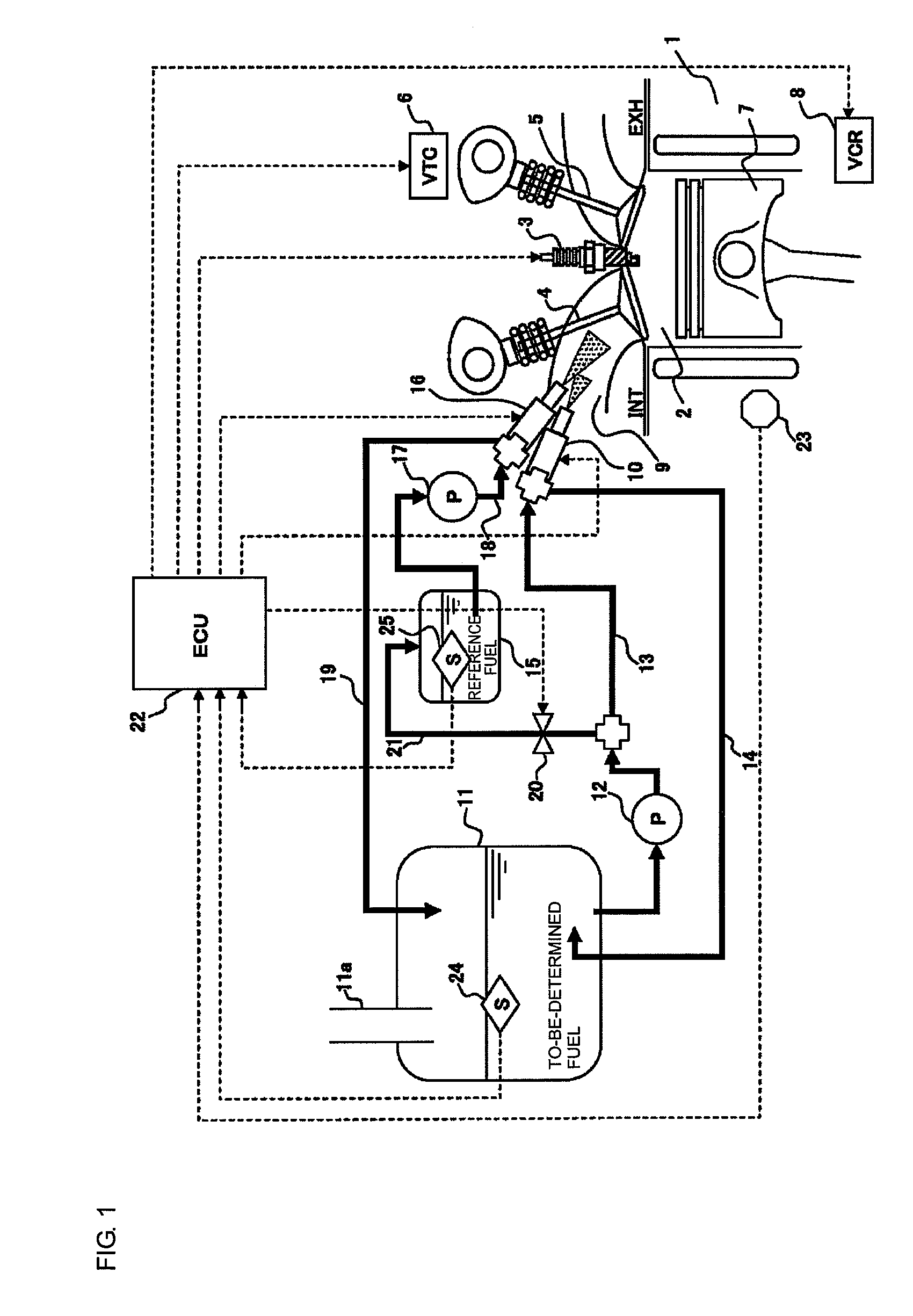
[0025]FIG. 1 is a system diagram showing a fuel supply system of an internal combustion engine according to the present invention.

[0026]The internal combustion engine 1 is a spark ignition type internal combustion engine having an ignition plug 3 within a combustion chamber 2. The internal combustion engine 1 also includes a variable valve timing mechanism (VTC) 6 capable of changing a valve timing of an intake valve 4 and an exhaust valve 5. Additionally, the internal combustion engine 1 includes a variable compression ratio mechanism (VCR) 8 capable of changing a compression ratio by changing the stroke amount of a piston 7.

[0027]A fuel is supplied to the internal combustion engine 1 by a fuel injection valve 10 disposed in an intake passage (intake port) 9. A fuel contained in a main tank 11 is supplied to the fuel injection valve 10 by a fuel pump 12 through a fuel passage 13, and excessive fuel is returned to the main tank 11 by a return passage 14.

[0028]A main tank 11 has a su...

second embodiment

[0075]Next, the present invention will be described with reference to FIG. 7.

[0076]In the first embodiment (FIG. 1), the fuel injection valve 10 for the to-be-determined fuel and the fuel injection valve 16 for the reference fuel are disposed on the intake air passage (intake air port) 9. According to the second embodiment (FIG. 7), the fuel injection valve 10 for the to-be-determined fuel is disposed in the intake air passage (intake air port) 9 while the fuel injection valve 16 for the reference fuel is disposed within the combustion chamber 2.

[0077]On the premise of a direct fuel injection type internal combustion engine, it is permissible to dispose both the fuel injection valve 10 for the to-be-determined fuel and the fuel injection valve 16 for the reference fuel within the combustion chamber 2, or to dispose the fuel injection valve 10 for the to-be-determined fuel within the combustion chamber 2 while the fuel injection valve 16 for the reference fuel is disposed in the inta...

third embodiment

[0079]Next, the present invention will be described with reference to FIG. 8.

[0080]The third embodiment includes a reformer for reforming a fuel and can determine the self-ignition property of the reformed fuel when the reformed fuel reformed by the reformer is supplied to an internal combustion engine.

[0081]A fuel is supplied to the internal combustion engine 1 by first and second fuel injection valves 31, 32 disposed in the intake air passage 9.

[0082]Fuel in the main tank 11 is supplied to first and second reformers (reformation catalyst) 34, 35 by the fuel pump 12 through a fuel passage 33. The first reformer 34 generates a fuel having a relatively low self-ignition property (high octane number, low cetane number, hereinafter referred to as high octane number) by reforming the fuel, and the second reformer 35 generates a fuel having a relatively high self-ignition property (low octane number, high cetane number, hereinafter referred to as low octane) by reforming the fuel.

[0083]T...


PUM

PropertyMeasurementUnit
octane numberaaaaaaaaaa

Abstract

A spark-ignition type internal combustion engine, including a main tank for storing a to-be-determined fuel having an unknown self-ignition property, an auxiliary tank for accumulating a reference fuel having a known self-ignition property, and a controller. The controller is programmed to supply to a combustion chamber a blended fuel prepared by blending the to-be-determined fuel and the reference fuel at a predetermined ratio, measure a self-ignition property of the blended fuel, and determine the unknown self-ignition property of the to-be-determined fuel based on the measured self-ignition property of the blended fuel, the known self-ignition property of the reference fuel and the ratio of the blended fuel. The controller is also programmed to introduce the to-be-determined fuel after the determination from the main tank to the auxiliary tank, and store the to-be-determined fuel in the auxiliary tank such that the to-be-determined fuel serves as a next reference fuel having a known self-ignition property.

Description

CROSS-REFERENCE TO RELATED APPLICATIONS[0001]This application claims priority to Japanese Patent Application No. 2007-061532, filed Mar. 12, 2007, the disclosure of which is incorporated by reference herein in the entirety.BACKGROUND OF THE INVENTION[0002]1. Field of the Invention[0003]The present invention relates to a spark ignition type internal combustion engine which determines (estimates) the self-ignition property of a fuel whose property is unknown.[0004]2. Description of Related Art[0005]Determining the self-ignition property (i.e. characteristic indicating the self-ignition property represented by octane number or cetane number) of a fuel using knocking determination (i.e. measurement of knocking limit ignition timing) is a well-known technology in the field of the spark ignition type internal combustion engine. Such determining has been widely used in discriminating high-octane gasoline from regular gasoline.[0006]A related art spark ignition type internal combustion engi...

Claims


Application Information

Patent Timeline
Patent Type & Authority Patents(United States)
IPC IPC(8): G01N33/22
CPCF02D19/08F02D19/12F02D35/027F02D41/0025F02M25/14F02M37/0064Y02T10/36F02M69/044F02D2200/0612Y02T10/30
Inventor ASHIDA, KOICHINODA, TORUHOTTA, ISAMU
Owner NISSAN MOTOR CO LTD
Learn More