
Connector

a technology of connecting rods and connectors, applied in the direction of coupling device connection, connection contact member material, coupling protective earth/shielding arrangement, etc., can solve the problems of difficult formation, unusable enlargement of ground terminals, complex ground terminals, etc., and achieve the effect of facilitating production

Inactive Publication Date: 2009-06-30
SUMITOMO WIRING SYST LTD
View PDF9 Cites 1 Cited by
  • Summary
  • Abstract
  • Description
  • Claims
  • Application Information

AI Technical Summary

Benefits of technology

The invention is a connector with a housing that can be mounted on an electrically conductive bracket. The connector includes terminal fittings to be connected with cables, including ground wires. The terminal fittings have split ground terminals with at least one circuit-side contact to be connected with the ground wire and / or a terminal fitting connected with the ground wire. The split ground terminals are small and simple to facilitate production. The housing has a partition to position the bracket and the split ground terminals. The bracket and the split ground terminals are mounted into the housing in the same direction. The bracket-side contacts are in one direction and are brought into contact with the same plate surface of the bracket. The terminal fittings are arranged at plural levels in the housing and the bracket-side contacts are brought into contact with the bracket at symmetrical positions. The terminal fittings are retained by terminal-fitting retaining pieces that resiliently engage the mounted terminal fittings. The housing has terminal-fitting retaining pieces at sides of the terminal fittings opposite the circuit-side contacts. The housing also has a bracket lock for locking the bracket. The bracket lock is at a side of the bracket opposite the bracket-side contacts. These features improve the arrangement efficiency and make the connector more compact.

Problems solved by technology

This arrangement requires an undesirable enlargement of the ground terminal.
Thus, the ground terminal becomes complicated and is difficult to form by press working.
Furthermore, the complex ground terminals are not easily formed as a chain that can be formed into a hoop.

Method used


Image

  • Connector
  • Connector
  • Connector

Examples


Embodiment Construction

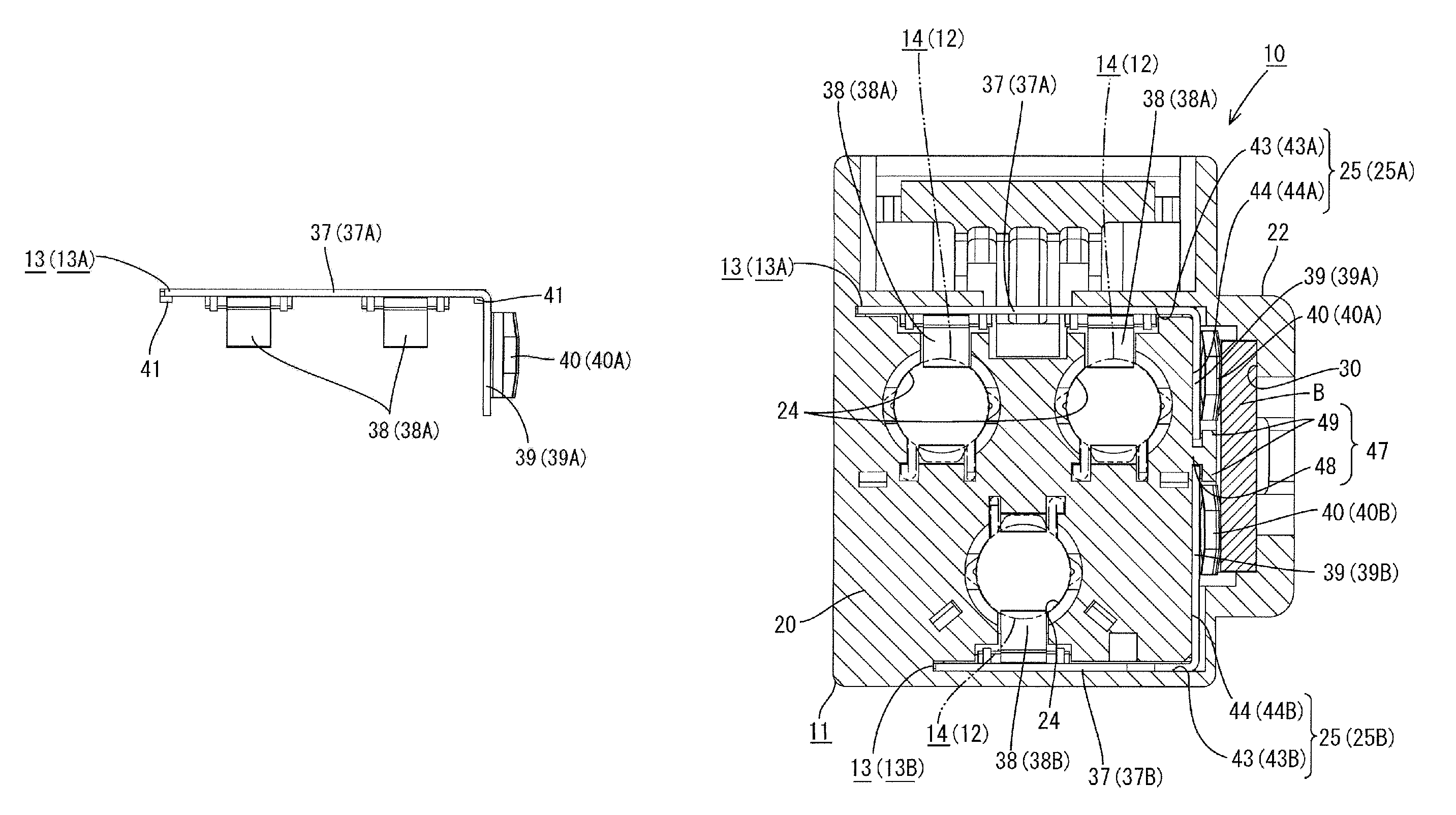
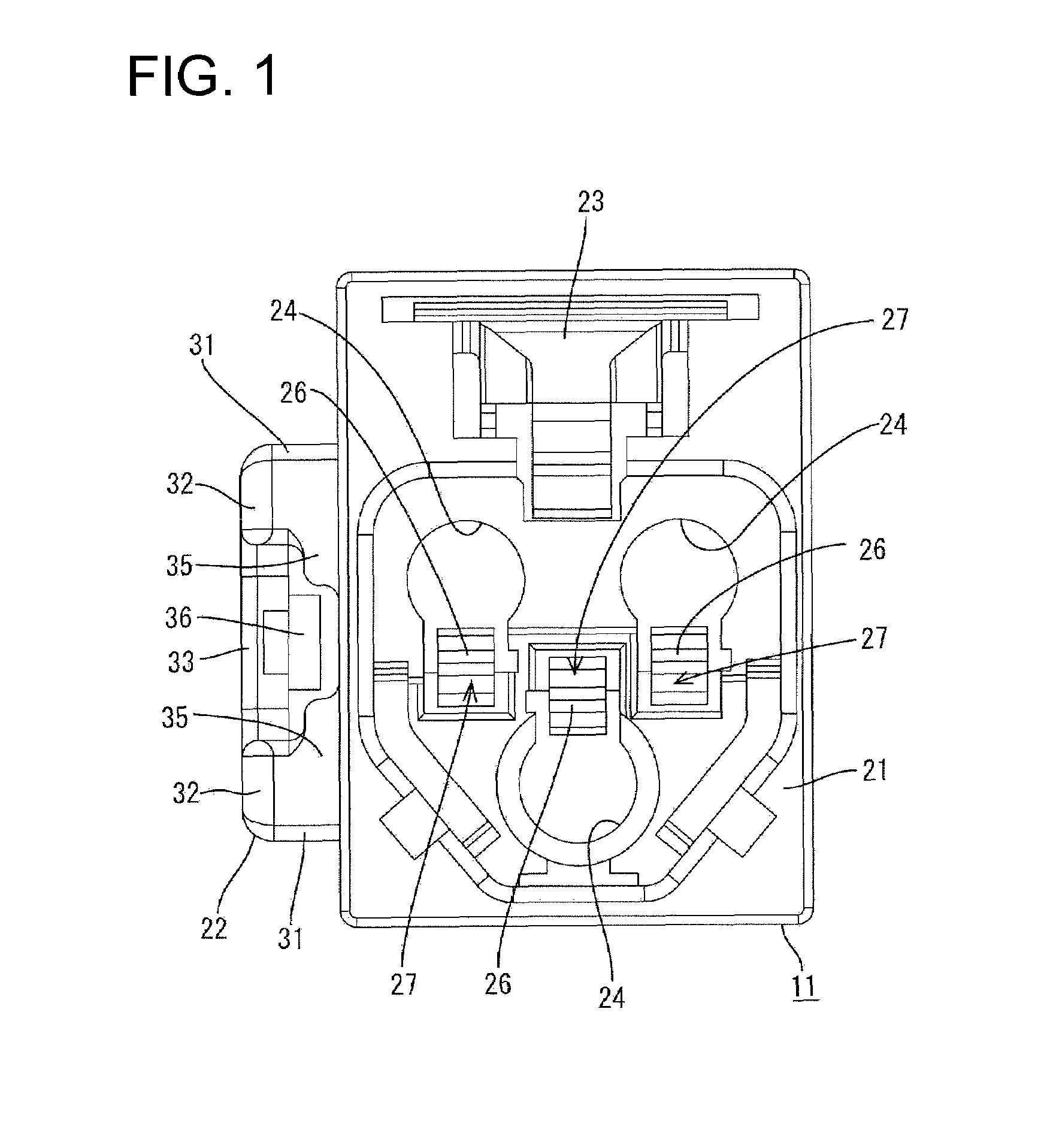
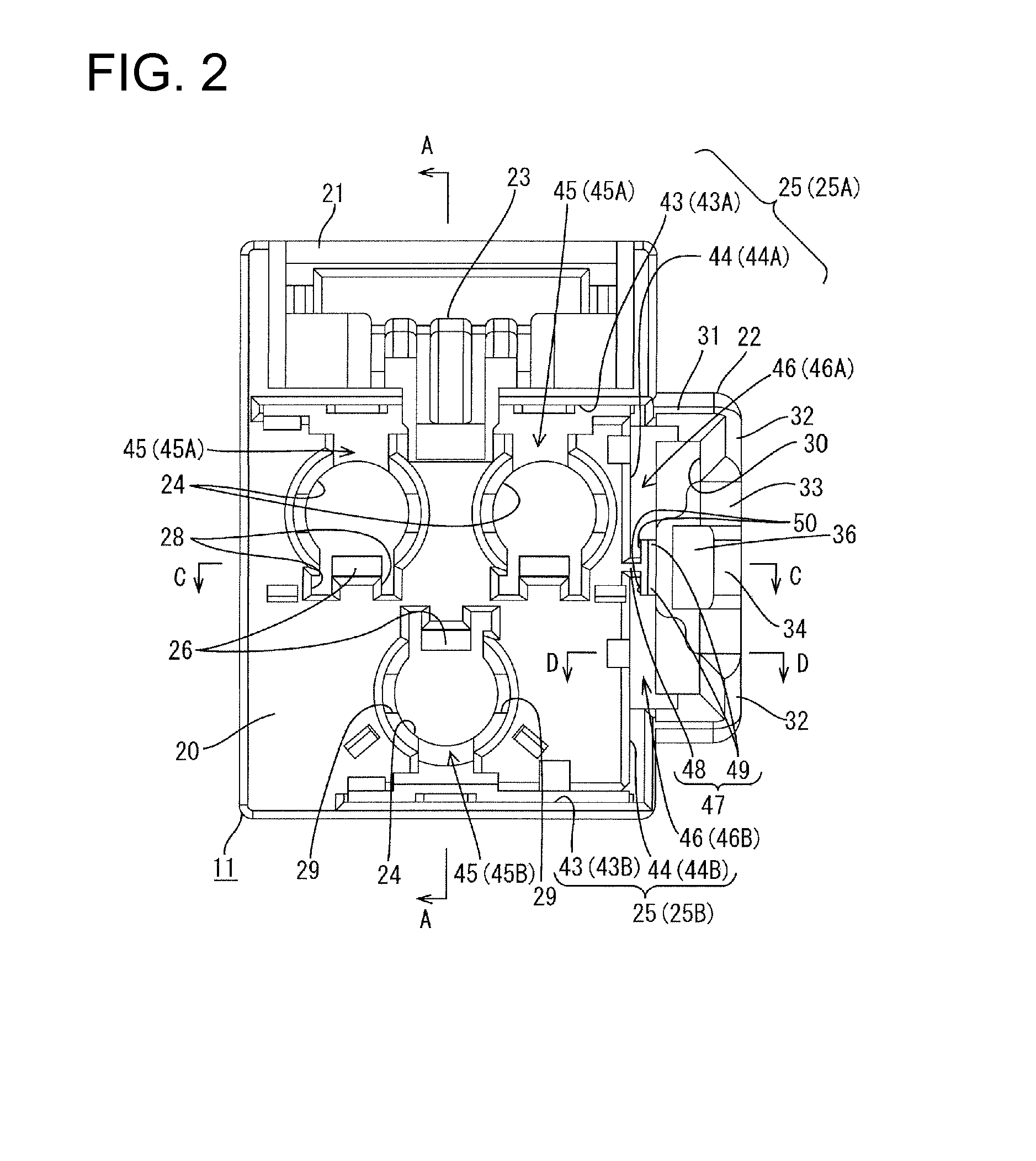
[0037]A connector in accordance with the invention is described with reference to FIGS. 1 to 20 and is identified by the numeral 10 in FIGS. 12 to 14 and 19. The connector 10 is to be mounted on a bracket B that is fixed or fixable to a body of an automotive vehicle (not shown). In the following description, an inserting direction of terminal fittings 12 and the bracket B (leftward direction in FIG. 12) is referred to as the forward direction, the opposite direction (rightward direction in FIG. 12) as a rearward direction. Additionally, reference is made to FIGS. 2 and 12 concerning the vertical direction. The terminal fittings 12 are not shown in FIGS. 15 and 16.

[0038]The bracket B is made of an electrically conductive material (such as metal) and defines a wide plate that projects from a position fixed to the body, as shown in FIGS. 3 and 15. A lock hole Ba penetrates the bracket B in the thickness direction at a widthwise intermediate position near the leading end. The leading en...


PUM


Abstract

A connector (10) is provided with a housing (11) to be mounted on an electrically conductive bracket (B), a plurality of terminal fittings (12) connected with coaxial cables each including an outer conductor as a ground wire and to be mounted in the housing (11), and a plurality of split ground terminals (13) to be mounted in the housing (11) and including circuit-side contact pieces (38) to be brought into contact with outer conductor terminals (14) of the terminal fittings (12) connected with the outer conductors and bracket-side contact pieces (40) to be brought into contact with the bracket (B).

Description

BACKGROUND OF THE INVENTION[0001]1. Field of the Invention[0002]The invention relates to a connector.[0003]2. Description of the Related Art[0004]U.S. Pat. No. 5,433,633 relates to a connector with a ground terminal for connection of a ground wire included in an electric wiring of an automotive vehicle to a body. The connector includes a housing to be mounted on a bracket fixed to the vehicle body. The connector also includes a terminal fitting and a ground terminal in the housing. The terminal fitting is connected with an inner conductor of a coaxial cable and the ground terminal connects an outer conductor (ground wire) of the coaxial cable to the bracket that is fixed to the vehicle body. The ground terminal is inserted into the housing and includes a circuit-side contact to be brought into contact with the outer conductor and a bracket-side contact to be brought into contact with the bracket.[0005]Plural terminal fittings may be accommodated in a housing and outer conductors of ...

Claims


Application Information

Patent Timeline
Patent Type & Authority Patents(United States)
IPC IPC(8): H01R4/48H01R4/64H01R13/648
CPCH01R13/65802H01R13/73H01R9/05H01R13/6582H01R13/6592H01R13/6596Y10S439/939H01R4/66
Inventor IMAI, YUUJIROU
Owner SUMITOMO WIRING SYST LTD
Learn More