
Method and apparatus for controlling a smart antenna using metrics derived from a single carrier digital signal

a technology of digital signal and smart antenna, applied in the direction of site diversity, spatial transmit diversity, polarisation/directional diversity, etc., can solve the problems of multipath interference, low gain of antennae, and difficult reception of single carrier digital tv signals using indoor antennas

Active Publication Date: 2009-06-23
ATI TECH INC
View PDF18 Cites 3 Cited by
  • Summary
  • Abstract
  • Description
  • Claims
  • Application Information

AI Technical Summary

Benefits of technology

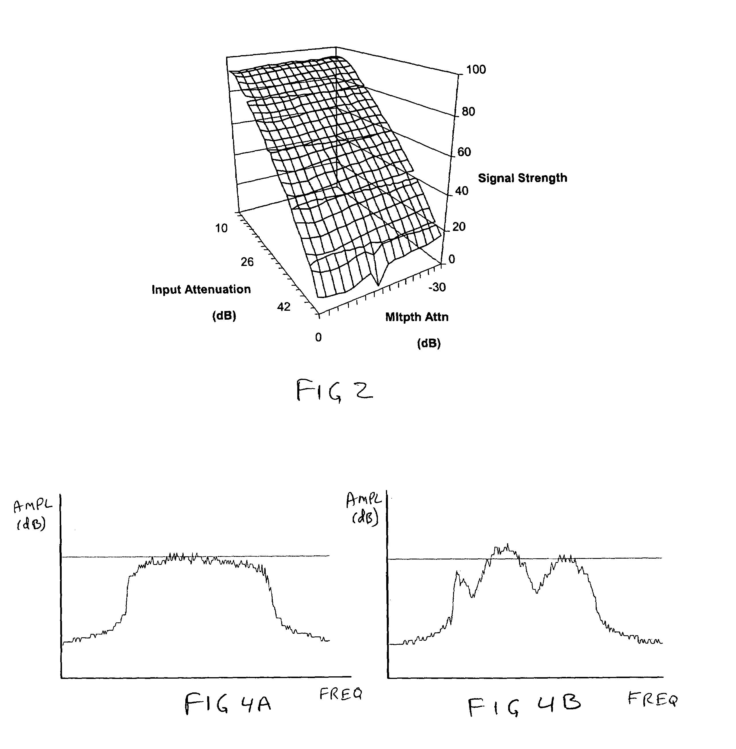
[0016]b) a MMSE (DFE) channel quality metric. This measure corresponds to the theoretical Minimum Mean Square Error (MMSE) when a Decision Feedback Equalizer (DFE) is used to equalize the channel. The measure can be expressed in the frequency domain or in the time domain. Either approach may be explicitly used in this invention. Furthermore, if required, additional simplifications may be introduced to further reduce computational time.

Problems solved by technology

Reliable reception of single carrier digital TV (DTV) signals using indoor antennae poses a technical challenge.
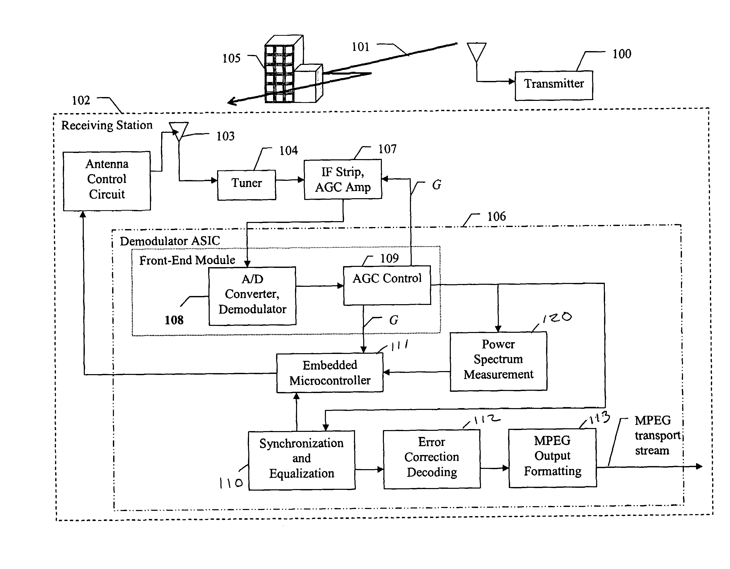
Topology, including terrain and buildings, create multiple paths that each transmitted signal may take from transmitter to receiver, resulting in an impairment phenomenon known as “multipath interference.” The receiver must discriminate among multiple time and phase shifted versions of the same transmitted signal.
Unfortunately, these antennae tend to exhibit fairly low gain, and tend to exacerbate multipath problems.
It is unreasonable to expect a consumer, using a remote-control to change channels, to manually change the direction of an antenna just to be able to receive a new channel.
The challenge is to develop a system for selecting the proper antenna or combination of antennae, with the proper gain, to give the best TV reception.
While this satisfies the requirement for automatic control, it cannot provide a decision quickly enough for a commercial product.
Although this solution works well in many cases, it is not reliable.
Smart antenna problems can be divided into issues related to antenna calibration and issues related to an optimization of direction of arrival and / or minimization of undesirable interference by mean of an array of sensors.
Optimization of the directivity of an antenna for a wide band signal is generally a more challenging problem, which can often be merged with a channel equalization problem.

Method used


Image

  • Method and apparatus for controlling a smart antenna using metrics derived from a single carrier digital signal
  • Method and apparatus for controlling a smart antenna using metrics derived from a single carrier digital signal
  • Method and apparatus for controlling a smart antenna using metrics derived from a single carrier digital signal

Examples


Embodiment Construction

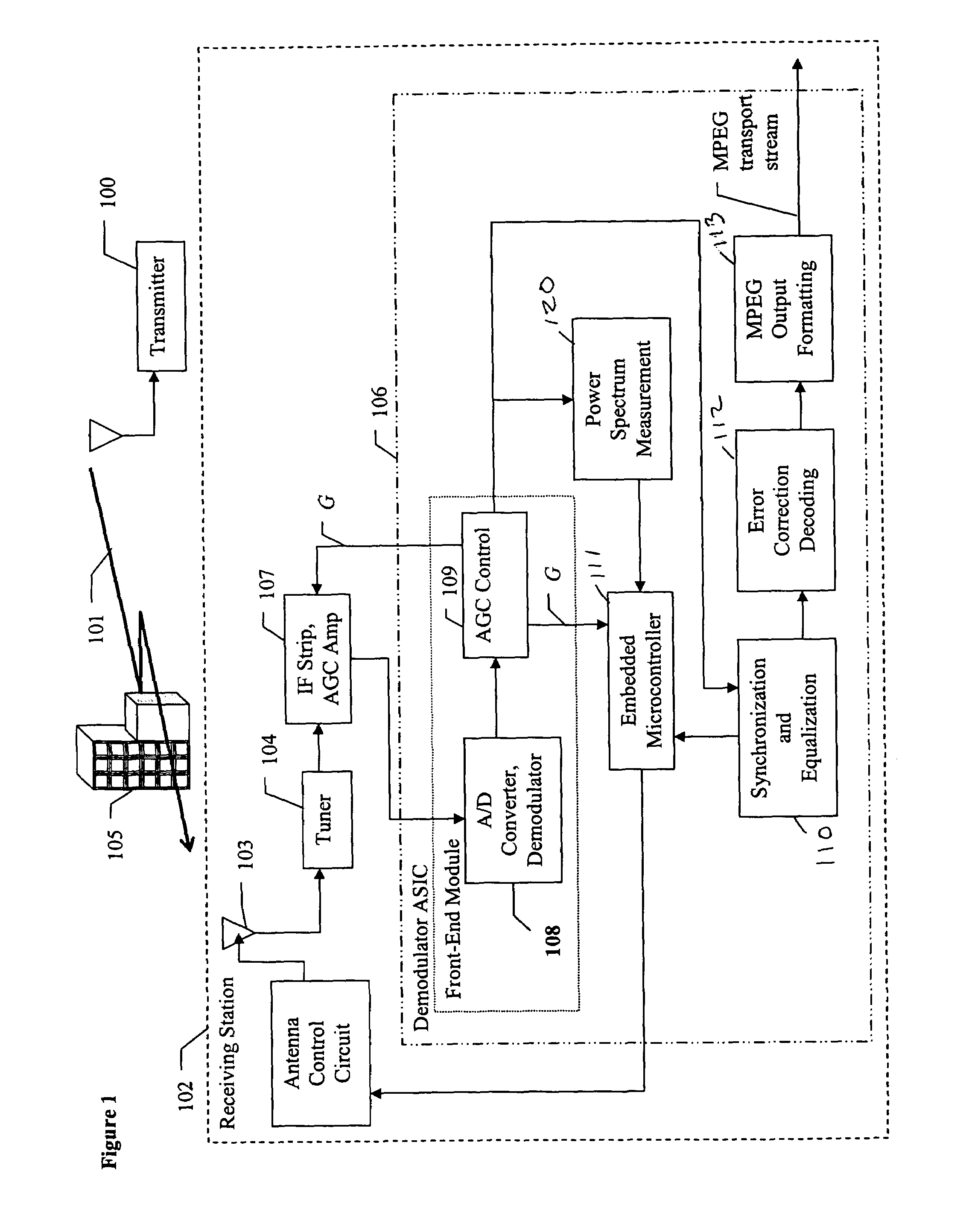
[0028]One element in a DTV receiver according to the subject invention, which is different from prior DTV receivers, is that the equalizer introduced to remove the multipath interference operates on a single signal, which is precisely the signal furnished by the optimum smart antenna. The optimization of the smart antenna uses the assumption that the demodulator applies the best possible equalizer (i.e. the one which provides the minimum bit error rate (BER)) associated with each possible antenna combination and each possible local DTV transmitted channel. In other words, the approach uses a two-step procedure. In a first step, the optimum smart antenna setting is deduced from the assumption that a theoretical optimum post processing equalizer will be applied to the signal, and in a second step the optimum equalizer (or a closed-form solution) is applied to the best received candidate signal. Metrics that confirm the optimum setting are then computed and fed back to the smart antenn...


PUM


Abstract

A method for selecting an antenna direction setting for optimum signal reception prior to channel equalization provides a set of metrics, referred to as channel quality metrics (CQM), that characterize the quality of the received signal for a given antenna setting and a generic algorithm that uses these metrics to select the antenna setting for an optimum reception. This invention utilizes five main CQMs: a Signal Strength Metric (SSM), a minimum mean squared error of a decision feedback equalizer (MMSE (DFE)) channel quality metric, a MMSE for a linear equalizer (MMSE(LE)) channel quality metric, a Spectral Flatness Metric (SFM) and an interference degradation metric (IDM).

Description

CROSS-REFERENCE TO RELATED APPLICATIONS[0001]This application claims the benefit of U.S. Provisional Application No. 60 / 475,736, filed Jun. 4, 2003, the contents of which are incorporated herein by reference.FIELD OF THE INVENTION[0002]The present invention relates to the optimum control of an electronically steerable antenna receiving a single carrier broadband digital signal. In particular, the present invention relates to the control of a smart antenna receiving high definition television (HDTV) signal such as that adopted by the U.S. for terrestrial broadcast transmission (ref. Doc / A53 HDTV standard, Advanced Television Systems Committee 1995). The invention is furthermore compliant with the EIA / CEA-909 antenna interface standard (EIA / CEA-909 Antenna Control Interface, 2002).BACKGROUND OF THE INVENTION[0003]Reliable reception of single carrier digital TV (DTV) signals using indoor antennae poses a technical challenge. A single reception site may be served by multiple transmitter...

Claims


Application Information

Patent Timeline
IPC IPC(8): H04B1/10H04B7/02H04B7/08
CPCH04B7/022H04B7/0811
Inventor REICHGOTT, SAMUEL H.CASAS, RAUL A.HULYALKAR, SAMIR N.TOUZNI, AZZEDINEZYGMANIAK, JOHN J.YOUTZ, ANDREW E.
Owner ATI TECH INC
Learn More