
System and method for recovering wasted energy from an internal combustion engine

a technology of internal combustion engine and waste energy, applied in the field of system and method, can solve the problems of affecting the efficiency or performance characteristics of such engines, failing to provide an internal combustion engine capable of operating on a six-stroke cycle, and immediately “flashing” into steam

Inactive Publication Date: 2009-06-23
SINGH SATNARINE
View PDF40 Cites 13 Cited by
  • Summary
  • Abstract
  • Description
  • Claims
  • Application Information

AI Technical Summary

Benefits of technology

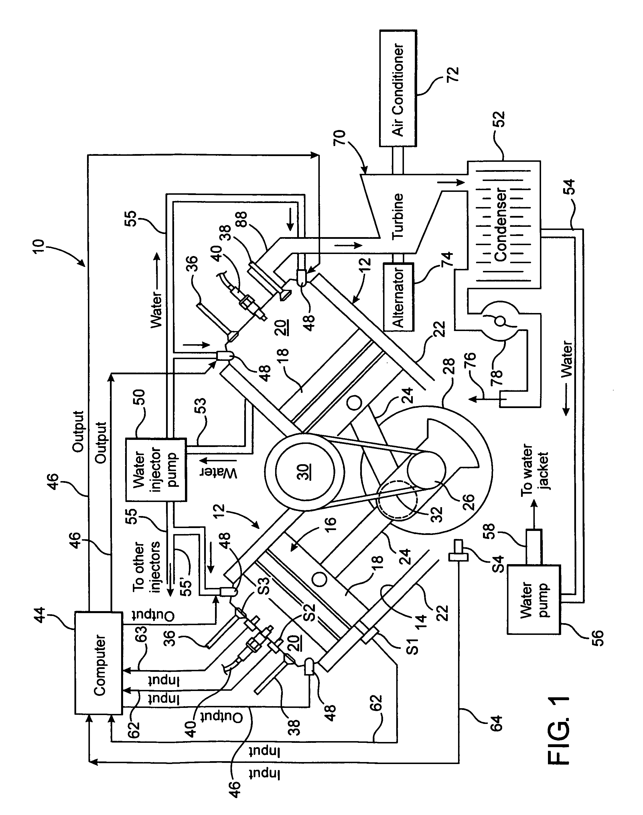
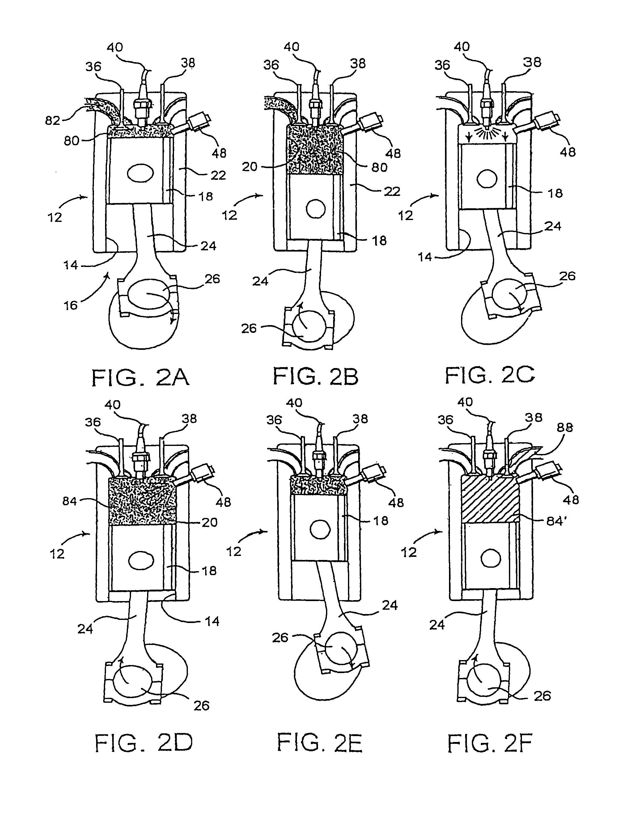
[0017]One or more preferred embodiments of the present invention are directed towards a computer controlled internal combustion (IC) engine, and its method of operation, designed to operate on a six-stroke cycle and specifically includes the injection of water into the combustion chamber or cylinder of each of a plurality of piston and cylinder assemblies, during a predetermined portion of the six-stroke cycle. More specifically, the quantity and timing of the water injection is controlled and regulated to the extent that the injected water is prevented from turning into steam even after reaching sufficiently high temperatures because of the continuously increasing pressure within the cylinder, due to the compression of gases therein, to the extent that the water is maintained in a liquid state until the beginning of an intended “auxiliary” power stroke.
[0021]In addition, one or more of the plurality of sensors are mounted on the engine to determine the engine speed as well as the temperature of the water being injected into the cylinder prior to its injection. The determination of the engine speed by the sensor assembly will, in turn, inform the central processor of the rate of travel of the pistons within respective ones of the cylinders. Since it is important that water, when injected into the cylinder absorb the maximum amount of heat without turning into steam, the determination of the central processor of the rate of travel of the piston within the cylinder will allow the central processor to determine the length of time a predetermined stroke exists. This in turn will allow the central processor to inject water into the cylinder at a time during a predetermined stroke that will allow the injected water to spend the maximum amount of time in the cylinder and thereby absorb the maximum amount of heat, without turning into steam. Informing the central processor of the amount of time the various quantities of injected water spend in the cylinder, absorbing heat, better assures that maximum heat energy is extracted, thereby resulting in a more efficient auxiliary power stroke being subsequently produced. The temperature of the water prior to it being injected into the cylinder will also be communicated to the central processor so as to aid in the calculation of the amount of heat required to convert the water into steam specifically during the second predetermined portion of the sixth stroke cycle.
[0028]Therefore, the improved IC engine of indicated preferred embodiments of the present invention will allow the development of significantly more power from relatively smaller size engines while operating at an increased efficiency level. The increase in efficiency will be due to the development of two power strokes using the same amount of combustible fluid or air-fuel mixture. The admission of pollutants into the atmosphere will also be reduced since the exhausting of the previously ignited combustible fluid only occurs at the end of the six-stroke cycle, along with the steam. Further, the resulting IC engine can operate on a lower compression ratio, thereby eliminating the necessity of using more expensive, high octane fuels. In addition to the above, the computer controlled IC engine of the present invention will be environmentally friendly by enabling the use of less combustible or fossil fuel, while allowing the engine to do a greater amount of work.
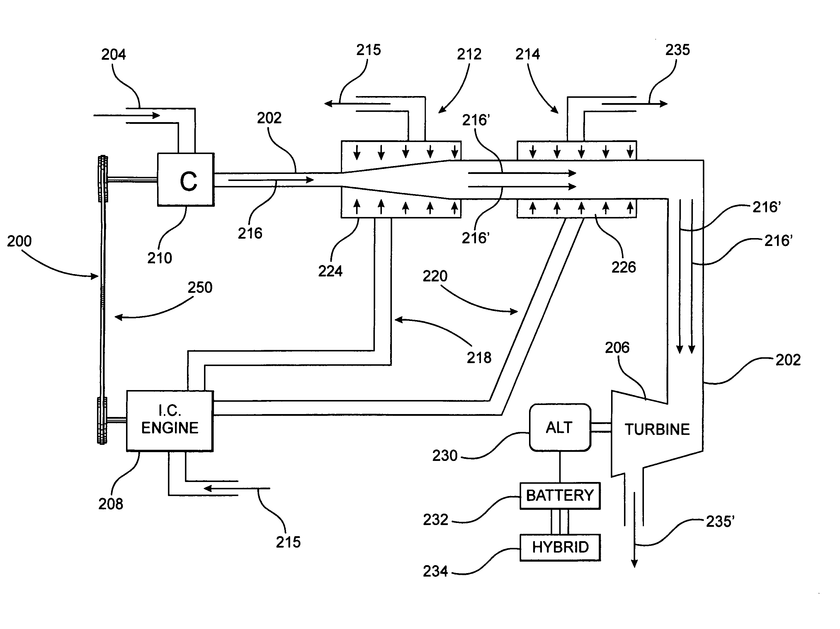
[0033]Naturally, the engine cannot be reduced in speed during the fourth stroke to permit the right amount of heat transfer to accomplish an efficient conversion of water to steam. Therefore, one preferred embodiment of the present invention is directed to a power generating assembly which overcomes the above set forth problem by comprising alternative power sources more specifically referred to hereinafter as a first power source and a second source. As such, the first power source, being an IC engine, may operate within a first speed range. The second power source, which may be generally referred to as a water injection engine is mechanically independent of the IC engine of the first power source. Therefore, the second power source may operate at a second speed range which is slower than that of the first speed range at which the IC engine operates. As such, the water to steam conversion process has sufficient time to absorb a requisite amount of heat to operate efficiently
[0037]As will also be explained in greater detail hereinafter, additional structural and operative features of the power generating assembly embodiment of the present invention include the source of electric energy being comprised of a generator and a battery assembly. Moreover, the second power source defined by the water injection engine is connected in direct driving relation to the generator. In turn, the generator is electrically connected to the battery assembly to facilitate and assure that the battery assembly will remain charged at all times in order that sufficient electric energy may be delivered to the electric motor on demand. Due to the fact that the second power source or water injection engine may operate independently of and therefore at a slower speed than the IC engine, sufficient time is provided for the injected water to absorb sufficient heat to be efficiently accomplish an effective water to conversion process and the development of sufficient power to drive the generator of the source of electric energy.
[0038]In this preferred embodiment the IC engine of the first power source and the water injection engine of the second power source are mounted on a common engine block. Such efficient structuring is due, at least in part, to a reduced size of the IC engine, which is made possible because the power demands of the vehicle are shared by both the IC engine and the electric motor. Further, each of the first and second power sources comprises at least one piston and cylinder assembly operative on a multi-stroke cycle, preferably such as a four stroke cycle, rather than the aforementioned six stroke cycle by which the preceding preferred embodiments of the present invention operate. Sufficient heat is transferred to the water injection engine to perform the water to conversion process by means of directing exhaust gas from the IC engine to the water injection engine. Other structural and operative features associated with an exhaust processing assembly are included in the power generating assembly embodiment of the present invention to assure that a sufficient quantity of exhaust gas, and therefore heat, is delivered to the water injection engine in an efficient and effective manner.

Problems solved by technology

Attempts to protect the environment have resulted in significant improvements in exhaust systems, fuel compositions and other operational components of modern IC engines, which sometimes derogatorily affect the efficiency or performance characteristics of such engines.
However, for the most part, such known attempts have failed to provide an internal combustion engine capable of operating on a six-stroke cycle, which is sufficiently efficient and effective for wide spread commercial use.
However, if the heated water were suddenly to be released from the closed container into atmosphere it would immediately “flash” into steam due to the significant drop in pressure.
Prior attempts to take advantage of the force generated when the water converts to steam in the combustion chamber or cylinder an IC engine have, for the most part, failed due to the fact that the water was injected and allowed to convert or “flash” into steam at the wrong time during the six-stroke cycle.
Allowing all of the water injected into a cylinder to simultaneously flash into steam would most probably result in damage to the engine due to the “instant” expansion force created.
Rather than developing a power stroke in the engine, such an expansive force would have a tendency to crack the engine block or cause a failure in the seals between the piston and the interior surface of the cylinder.
Another characteristic common to known attempts to develop a six-stroke cycle IC engine is the premature exhausting of the conventional air-fuel mixture after it has been ignited.

Method used


Image

  • System and method for recovering wasted energy from an internal combustion engine
  • System and method for recovering wasted energy from an internal combustion engine
  • System and method for recovering wasted energy from an internal combustion engine

Examples


Embodiment Construction

[0053]One or more preferred embodiments of the present invention are directed towards a computer controlled internal combustion (IC) engine, and its method of operation. Moreover, the subject IC engine is designed to operate on a six-stroke cycle and provide an auxiliary power stroke through the regulated injection of water into the combustion chamber or cylinder of one or more piston and cylinder assemblies of the engine and the conversion of the injected water into steam. It is emphasized that while related preferred embodiments of the present invention will be explained primarily with reference to a single piston and cylinder assembly, having an at least partially conventional design, the computer controlled IC engine of the present invention may be of the type incorporating one or a plurality of such piston and cylinder assemblies and may be specifically adapted for use as the power source in an automobile, truck or other motorized vehicle.

[0054]With primary reference to the FIG...


PUM


Abstract

An internal combustion engine and its method of operation including at least one embodiment operating on a six-stroke cycle and including at least one piston and cylinder assembly. The six-stroke cycle includes two power strokes, the latter of which is the result of a water to steam conversion process utilizing the heat of the exhaust gas from the first power stroke. A second embodiment comprises a hybrid power generating assembly incorporating alternative, first and second power sources respectively comprising an internal combustion engine and a water injection engine, the latter of which operates on the water to steam conversion process, wherein the required heat therefore is derived from the exhaust gas of the internal combustion engine. Another preferred embodiment comprises the utilization of different normally wasted heat sources from an IC engine for the generation of sufficient work energy to drive a power take-off, such as hybrid drive assembly.

Description

CLAIM OF PRIORITY[0001]The present application is a continuation-in-part application of previously filed, currently pending application having Ser. No. 10 / 453,238 filed on Jun. 3, 2003 now U.S. Pat. No. 7,021,272, which is a continuation-in-part application of previously filed application having Ser. No. 10 / 007,012 filed on Nov. 5, 2001, which matured into U.S. Pat. No. 6,571,749 on Jun. 3, 2003, which is a continuation-in-part application of previously filed application having Ser. No. 09 / 465,329, filed on Dec. 17, 1999 which matured into U.S. Pat. No. 6,311,651 on Nov. 6, 2001, wherein all of the above are incorporated herein in their entirety by reference.BACKGROUND OF THE INVENTION[0002]1. Field of the Invention[0003]At least one preferred embodiment of this invention relates to a computer controlled, internal combustion engine designed to operate on a six-stroke cycle, wherein water is injected into each of the one or more cylinders during a predetermined portion of the six-str...

Claims


Application Information

Patent Timeline
Patent Type & Authority Patents(United States)
IPC IPC(8): F02G5/00F02B1/04F02B3/06F02B47/02F02B75/02F02F1/24
CPCF02B41/10F02B47/02F02B75/021F02M25/03F02G5/04F02M25/0227F02G5/02F02B1/04F02B3/06F02F2001/247F02G2260/00Y02T10/121Y02T10/163Y02T10/166Y02T10/12
Inventor SINGH, SATNARINE
Owner SINGH SATNARINE
Learn More