
Particle-accelerating deposition and separation apparatus and method for turbid water

a separation apparatus and turbid water technology, applied in the direction of sedimentation settling tanks, liquid displacement, separation processes, etc., can solve the problems of affecting the purification function affecting the purification effect of water treatment facilities, and containing a tremendous amount of suspended particles on the surfa

Inactive Publication Date: 2009-06-16
LIU SHI PING
View PDF14 Cites 8 Cited by
  • Summary
  • Abstract
  • Description
  • Claims
  • Application Information

AI Technical Summary

Benefits of technology

[0015]Even though the size of a single water molecule is about 2 Å (1 Å=10−10 m), water molecules cannot move in the form of a single water molecule due to its polarity and hydrogen bonds. The water molecules often move in the form of water molecule clusters. The approximate size of a water molecule cluster depends on the flow velocity, water temperature, viscosity, dissolvent materials, and ion strength in the flow. Suppose that a water molecule cluster is in a spherical shape, and its diameter is around 0.02 μm. Because the specific gravity of the water molecular cluster is 1, the diffusion coefficient thereof at the temperature of 20° C. is 2.6×10⁻⁶ cm2 / sec, which is around 1,000 times that of a solid particle with a diameter of 1 μm. Accordingly, we can utilize the significant differences between the diffusion coefficients of a water molecule cluster and particles with various sizes to physically separate particles from clean water by making the particles settle vertically and water molecule clusters move horizontally.
[0018]Table 3 below shows the terminal settling velocity and the time needed for particles with various diameters to descend 1 meter at the temperature of 20° C. The VT of particles with a diameter of 100 μm is 100 times that of particles with a diameter of 10 μm. It takes around 3.4 hours for a 10 μm particle to descend 1 meter while it only takes around 2.1 minutes for a 100 μm particle to travel the same distance. Accordingly, the smaller the particle, the longer the time needed for the particles to settle in a pure gravity deposition system.
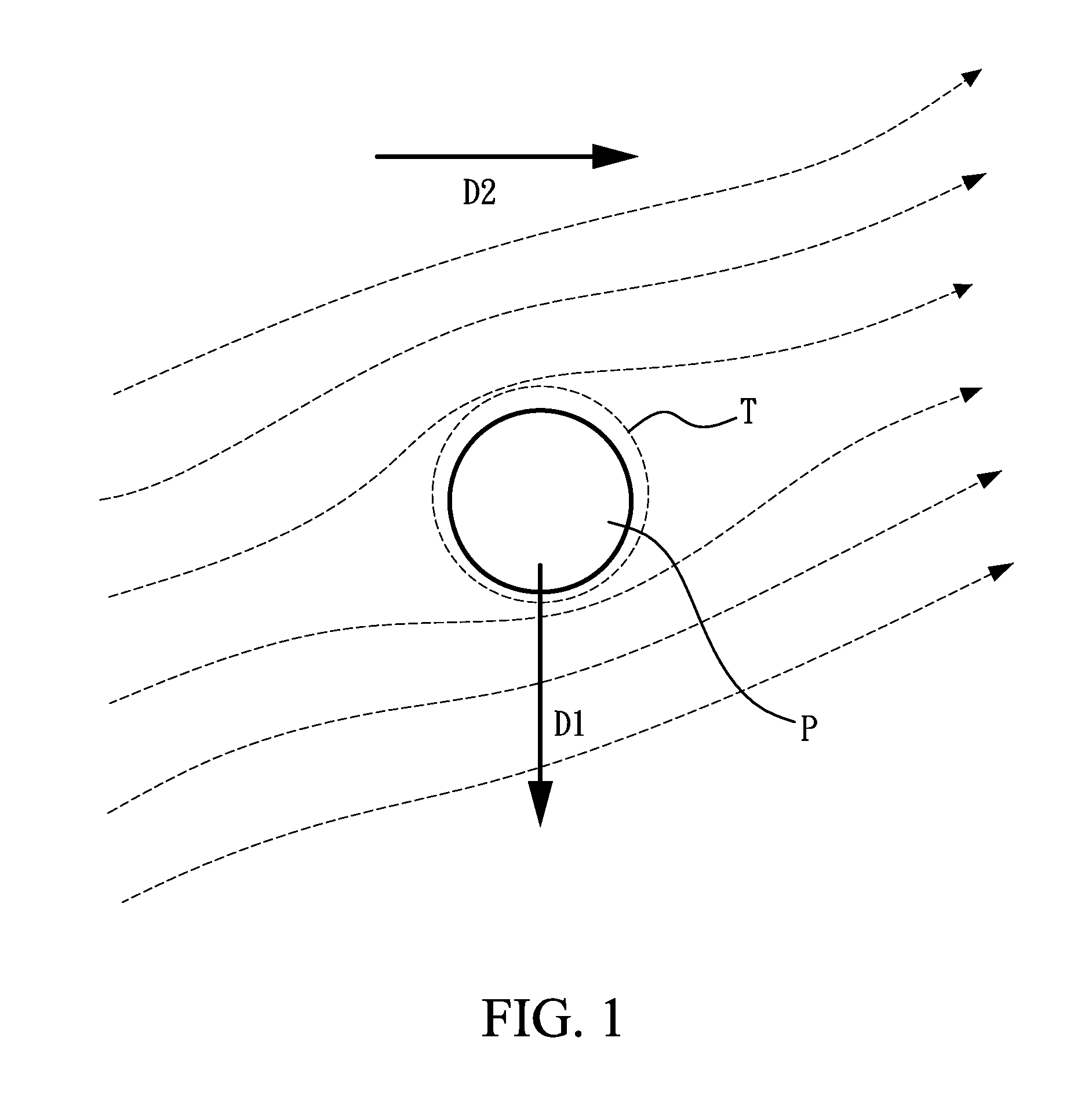
[0021]Please refer to FIG. 1, which is a schematic view of a vertically descending particle P and horizontally moving water molecule clusters (shown as the streamlines). The separation of the particle P and clean water can be described in terms of the relative movement therebetween. When the water molecule clusters move in the horizontal direction D2, they intersect the particle P. A stagnant layer T formed on the particle P prevents the water molecule clusters from directly colliding with the particle P so the water molecule clusters pass around the particle P. Therefore, the accelerating particle P that moves in the vertical direction D1 in accordance with the gravity will not be easily influenced by the horizontally moving water molecule clusters, and will thus depart from the particle-water separation area. Namely, when the water molecule clusters move in the horizontal direction D2, the streamlines will glide along the surface of the stagnant layer T formed on the particle P, and will not disturb the vertically descending particle P.

Problems solved by technology

However, heavy rainfall after natural disasters such as earthquake and hurricane and human activities such as over-development on hillsides and poor soil-and-water conservation may result in surface runoff containing tremendous amount of suspended particles in streams and subsequently lakes and dams.
The extra particle impurity causes high turbidity in raw water sources, which hinders the purifying functions in water treatment facilities and often temporarily disables water supply system in severe conditions.
Surface water movement after heavy rainfall washes soil particles from hillsides and disturbs sediments in the waterways results in a significant increase in the level of turbidity.
Removal of water turbidity is somehow difficult because the fine particles are most likely too tiny to settle effectively in the water treatment processes.
When water turbidity exceeds 2,000 nephelometric turbidity units (NTU), most water treatment facilities may experience clog malfunction in rapid sand filtration process.
If a rapid sand filtration pool is frequently clogged, back-wash is frequently required to restore its filtration function.
However, high frequency of back-wash significantly decreases the water quality.
However, chemical coagulation produces large amounts of sludge and reduces the density of the flocs, which hinders the deposition thereof.
Traditional water purifying process is unable to process such high-turbidity raw water by coagulation or gravity deposition.
The malfunction of water treatment plants caused by high turbid raw water will greatly affect water quality and may temporarily disrupt the water supply if the turbidity is extremely high.
Lack of water supply is detrimental to people's health and local economy.
The main characteristic of highly turbid raw water is excessive amount of suspended particles.
Highly turbid water requires large tracts of land for the installation of extra sedimentation and filtration facilities, which are difficult to acquire especially in metropolitan areas.
Further, the efficiency of the rapid sand filtration system in producing good quality and sufficient quantity of drinking water cannot be achieved without appropriate water turbidity pre-treatment process.
However, the centrifugal method consumes huge amount of electricity and requires large spaces while its turbidity removal efficiency is very low.
However, chemical coagulating agents produce large amount of sludge, which in turn becomes another pollution problem.

Method used


Image

  • Particle-accelerating deposition and separation apparatus and method for turbid water
  • Particle-accelerating deposition and separation apparatus and method for turbid water
  • Particle-accelerating deposition and separation apparatus and method for turbid water

Examples


Embodiment Construction

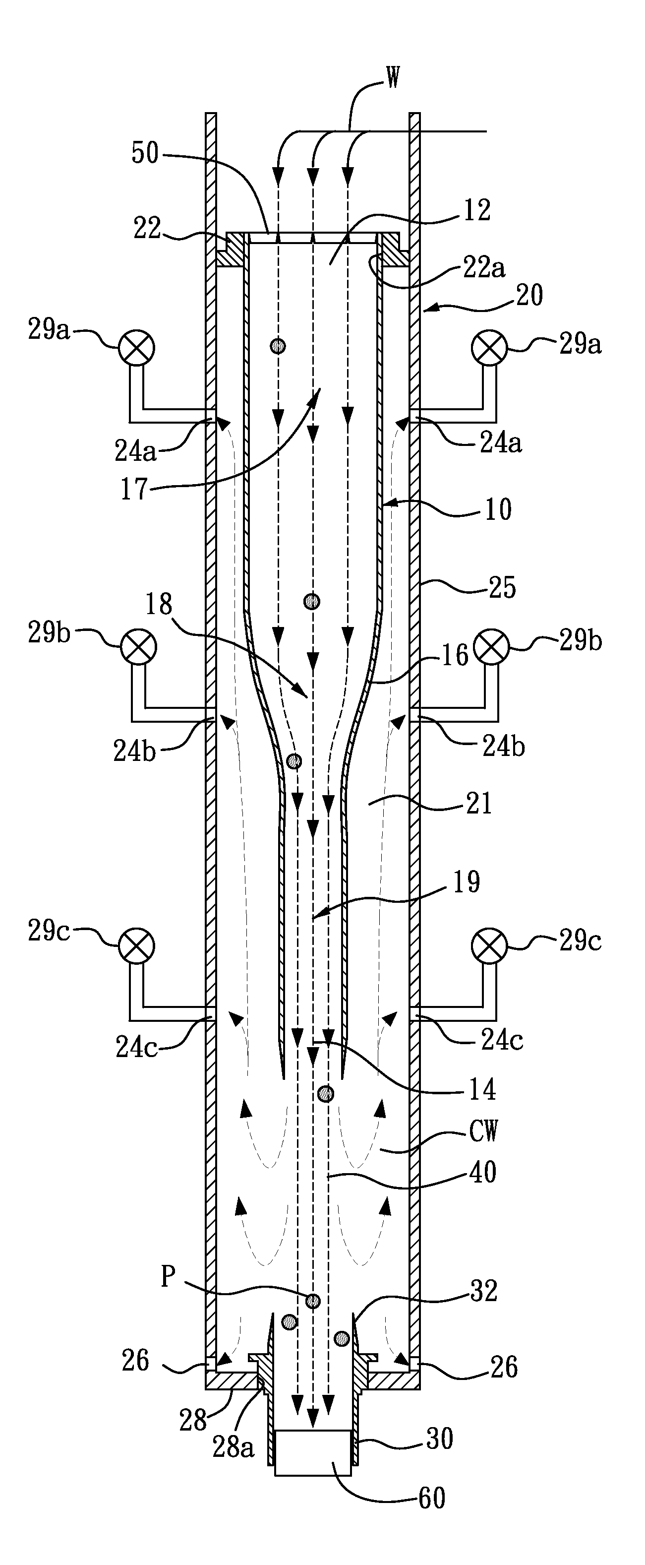
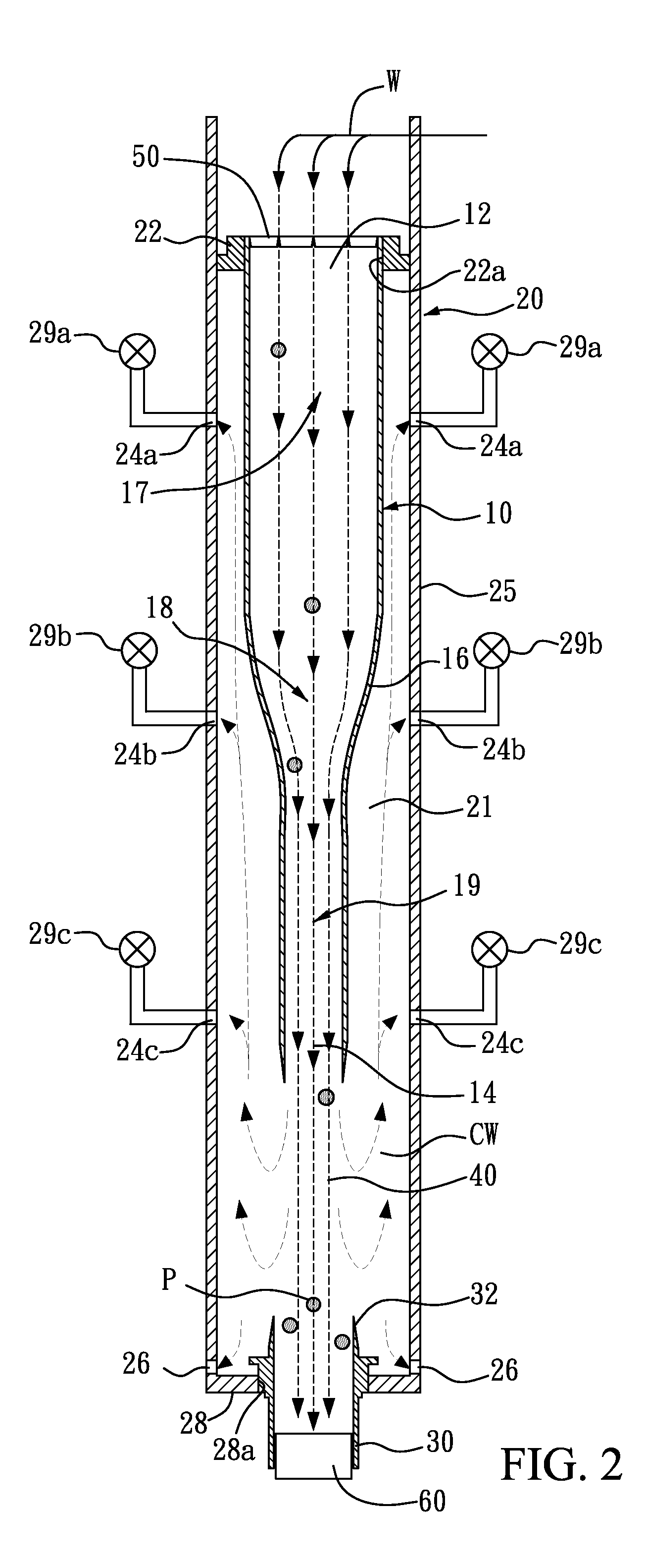
[0027]In FIGS. 2-3, the embodiment of the present invention relates to a particle-accelerating deposition and separation apparatus and method in an undisturbed laminar flow. The apparatus mainly contains: a housing 20, a hollow conical flow accelerator 10, a particle condenser 30, and a screen (i.e. a No. 200 screen 50). The housing 20 contains a hollow cylinder 25 provided with three clean water collecting pipes, namely the high, middle and low clean water collecting pipes 24a, 24b, 24c disposed on a peripheral wall thereof at various heights and equipped with at least one silt-removing outlet 26 on a bottom thereof. The hollow cylinder 25 has an inner diameter of approximately 15 centimeters and a height of approximately 105 centimeters, and can sustain the water pressure at a depth of 1.5 meters. The hollow cylinder 25 is 1 cm thick, made of acrylic, stainless steel, PVC or other materials with a smooth internal surface, and suitable for long-term continuous use with high-turbidi...


PUM

PropertyMeasurementUnit
heightaaaaaaaaaa
heightaaaaaaaaaa
inner diameteraaaaaaaaaa

Abstract

A pretreatment particle-accelerating deposition and separation apparatus and method for purifying turbid raw water, which based on the theories of laminar flow requirement, particle-accelerating vertical deposition and water horizontal movement, separates water molecules from turbidity particles in a laminar flow region (with a Reynolds number lower than 1,000). By accelerating the velocity of high-turbidity raw water and the turbidity particles, the particles settle vertically because of inertia. Thus, the turbidity particles can be removed physically from the raw water and clean water can be collected at different heights of the apparatus while concentrated turbid water can be released to a nearby body of water after appropriate treatments. Thereby, turbid water can be purified for the subsequent coagulation, sedimentation and filtration processes in traditional water treatment plants.

Description

FIELD OF THE INVENTION[0001]This invention relates generally to a particle-accelerating deposition and separation apparatus and method, in particular to a deposition and separation apparatus and method that physically separate particles from clean water in turbid raw water.BACKGROUND OF THE INVENTION[0002]Water supply is an important indication of modernization of a society. It not only influences general public health, industrial developments and commercial prosperity but also affects people's daily life. Therefore, supplying high-quality, safe and sufficient drinking water is one of a government's most important tasks. Conventional water treatments depend on good-quality raw water and stable purifying facilities to provide hundreds of thousands tons of drinking water that meets the drinking water standards. However, heavy rainfall after natural disasters such as earthquake and hurricane and human activities such as over-development on hillsides and poor soil-and-water conservation...

Claims


Application Information

Patent Timeline
Patent Type & Authority Patents(United States)
IPC IPC(8): B01D43/00B01D21/00
CPCB01D21/0024B01D21/0087B01D21/2427B01D2221/12B01D21/34
Inventor LIU, SHI-PING
Owner LIU SHI PING
Learn More