
Light emitting diode assemblies for illuminating refrigerated areas

a technology of light-emitting diodes and assembly parts, which is applied in the field of illumination panels, can solve the problems of reducing the life of lamps when operated, not efficiently illuminated food products, and reducing the light output of fluorescent lighting, so as to achieve the effect of minimal maintenance and very efficient operation

Inactive Publication Date: 2008-08-07
AWAI GEORGE K +2
View PDF14 Cites 36 Cited by
  • Summary
  • Abstract
  • Description
  • Claims
  • Application Information

AI Technical Summary

Benefits of technology

[0007]To achieve the foregoing and in accordance with the present invention, light emitting diode (LED) assemblies for illuminating refrigerated display areas are provided. Such LED assemblies can be operated very efficiently, cost-effectively and with minimal maintenance once installed in the field.

Problems solved by technology

Although fluorescent lighting generate less heat and are more efficient than incandescent lighting, fluorescent lighting suffer from decreased light output and reduced lamp life when operated in cold temperature environments.
Florescent lighting also produces diffused light patterns and hence do not illuminate the food products efficiently.
Recent attempts at replacing florescent lighting with LEDs resulted in very limited success for several reasons.
While the compact size and durability of LEDs makes them suitable for compact edge lighting for illuminated display doors, LEDs, especially high-powered LEDs, generate a substantial amount of heat which substantially increase cooling load of the refrigerated areas.

Method used


Image

  • Light emitting diode assemblies for illuminating refrigerated areas
  • Light emitting diode assemblies for illuminating refrigerated areas
  • Light emitting diode assemblies for illuminating refrigerated areas

Examples


Embodiment Construction

[0024]The present invention will now be described in detail with reference to several embodiments thereof as illustrated in the accompanying drawings. In the following description, numerous specific details are set forth in order to provide a thorough understanding of the present invention. It will be apparent, however, to one skilled in the art, that the present invention may be practiced without some or all of these specific details. In other instances, well known process steps and / or structures have not been described in detail in order to not unnecessarily obscure the present invention. The features and advantages of the present invention may be better understood with reference to the drawings and discussions that follow.

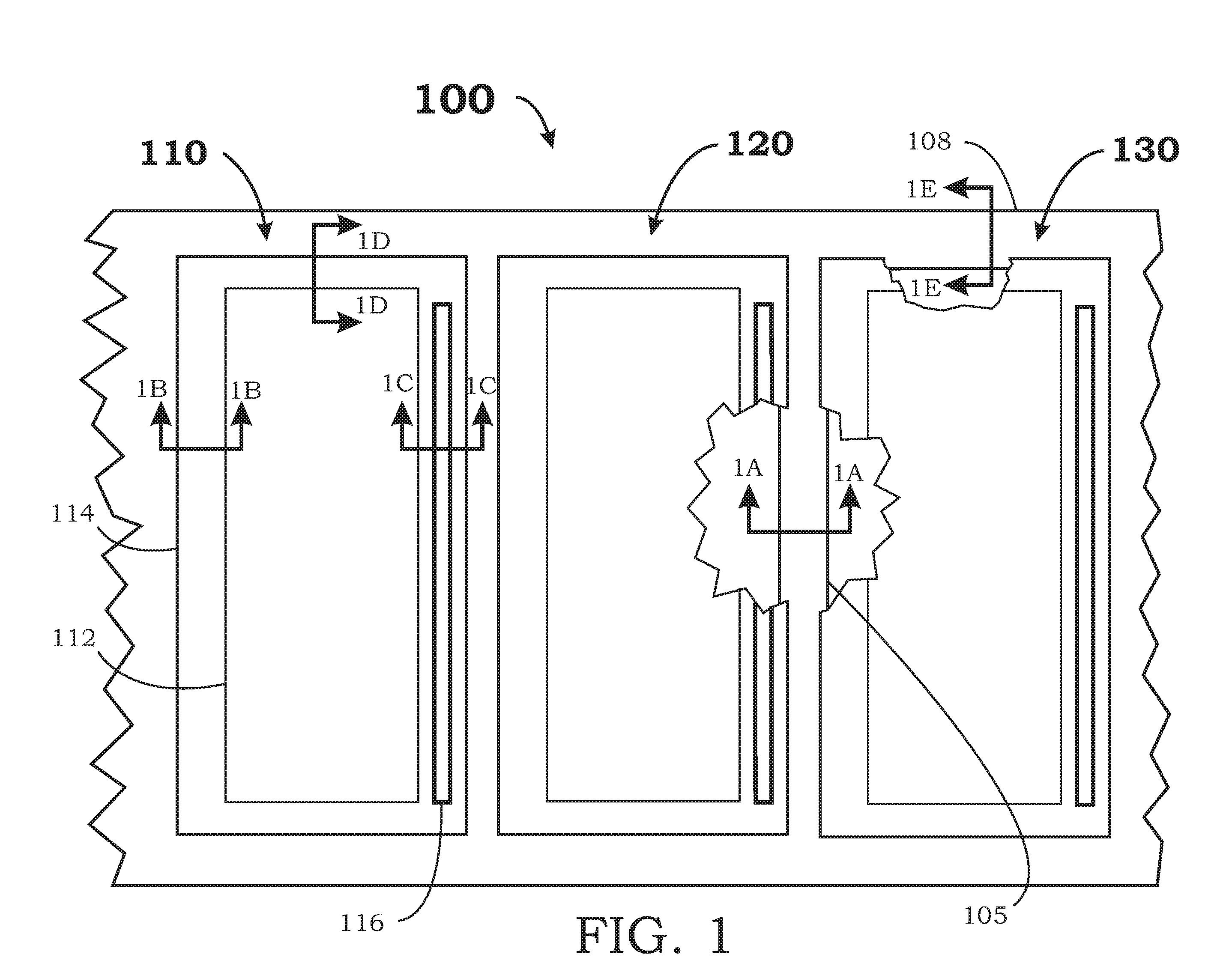
[0025]In accordance with the present invention, FIG. 1 is a front view showing an illuminated refrigerated display area 100 with a plurality of doors including doors 110, 120, 130. Door 110 includes a transparent panel 112, a frame 114 and a door handle 116. For...


PUM


Abstract

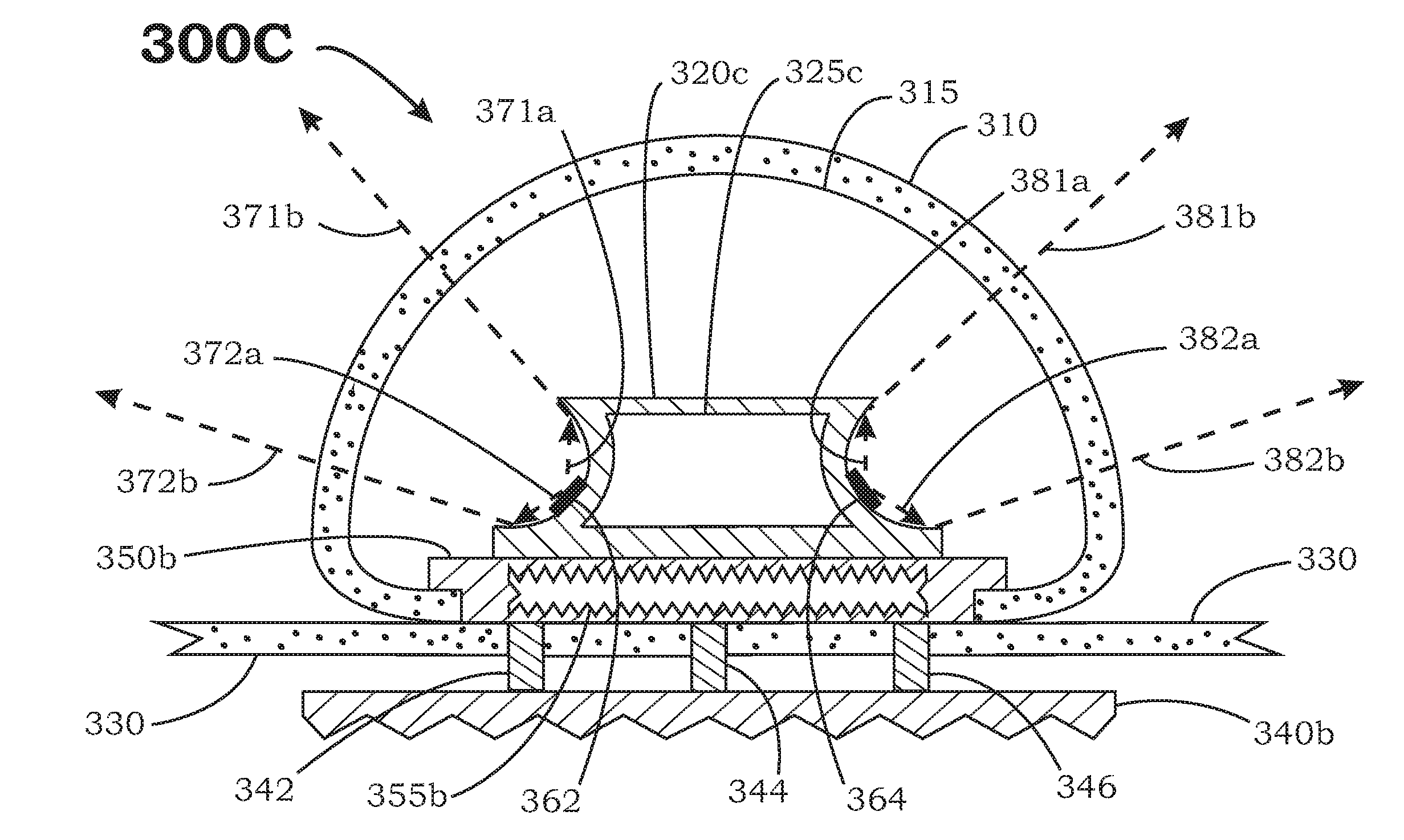
An LED assembly for illuminating a refrigerated area includes a plurality of LED modules and a reflector base configured to reflect light generated by the plurality of LED modules into the refrigerated area. The reflector base is further configured to conduct heat away from the plurality of LED modules and also includes a base cooling channel. Both the reflector base and the plurality of LED modules are located substantially within the refrigerated area. The LED assembly also includes an external heat sink coupled to the reflector base, and configured to conduct heat away from the reflector base, wherein the external heat sink is further configured to be mounted substantially outside the refrigerated area. The LED assembly can include a doom lens that forms a doom cooling channel substantially enclosing the reflector base. This internal heat sink includes an internal sink cooling channel.

Description

CROSS REFERENCE TO RELATED APPLICATIONS[0001]This is a continuation-in-part application of U.S. application Ser. No. 11 / 670,981, filed on Feb. 3, 2007, pending, and entitled “Light Emitting Diode Modules for Illuminated Panels”, incorporated by reference in its entirety; and co-pending and concurrently filed application Ser. No. ______, (Attorney Docket No. IM 0702) filed Mar. 29, 2007, entitled “Light Emitting Diode Waveguide Assemblies for Illuminating Refrigerated Areas”, by George K. Awai, Michael D. Ernst and Alain S. Corcos, which is incorporated by reference herein for all purposes.BACKGROUND OF THE INVENTION[0002]This invention relates generally to illuminating panels. More particularly, this invention relates to light emitting diode (LED) modules for illuminating refrigerated areas.[0003]Refrigerated display areas, such as supermarket freezers, make use of interior case lighting to illuminate products and to attract shoppers. In addition, the lighting should generate minima...

Claims


Application Information

Patent Timeline
Patent Type & Authority Applications(United States)
IPC IPC(8): F25D27/00
CPCF25D27/005G02B6/0085G02B6/001F25D2700/04
Inventor AWAI, GEORGE K.ERNST, MICHAEL D.CORCOS, ALAIN S.
Owner AWAI GEORGE K
Learn More