
Isolated working chamber associated with a secure inter-company collaboration environment

Inactive Publication Date: 2009-06-09
CADENCE DESIGN SYST INC
View PDF12 Cites 7 Cited by
  • Summary
  • Abstract
  • Description
  • Claims
  • Application Information

AI Technical Summary

Benefits of technology

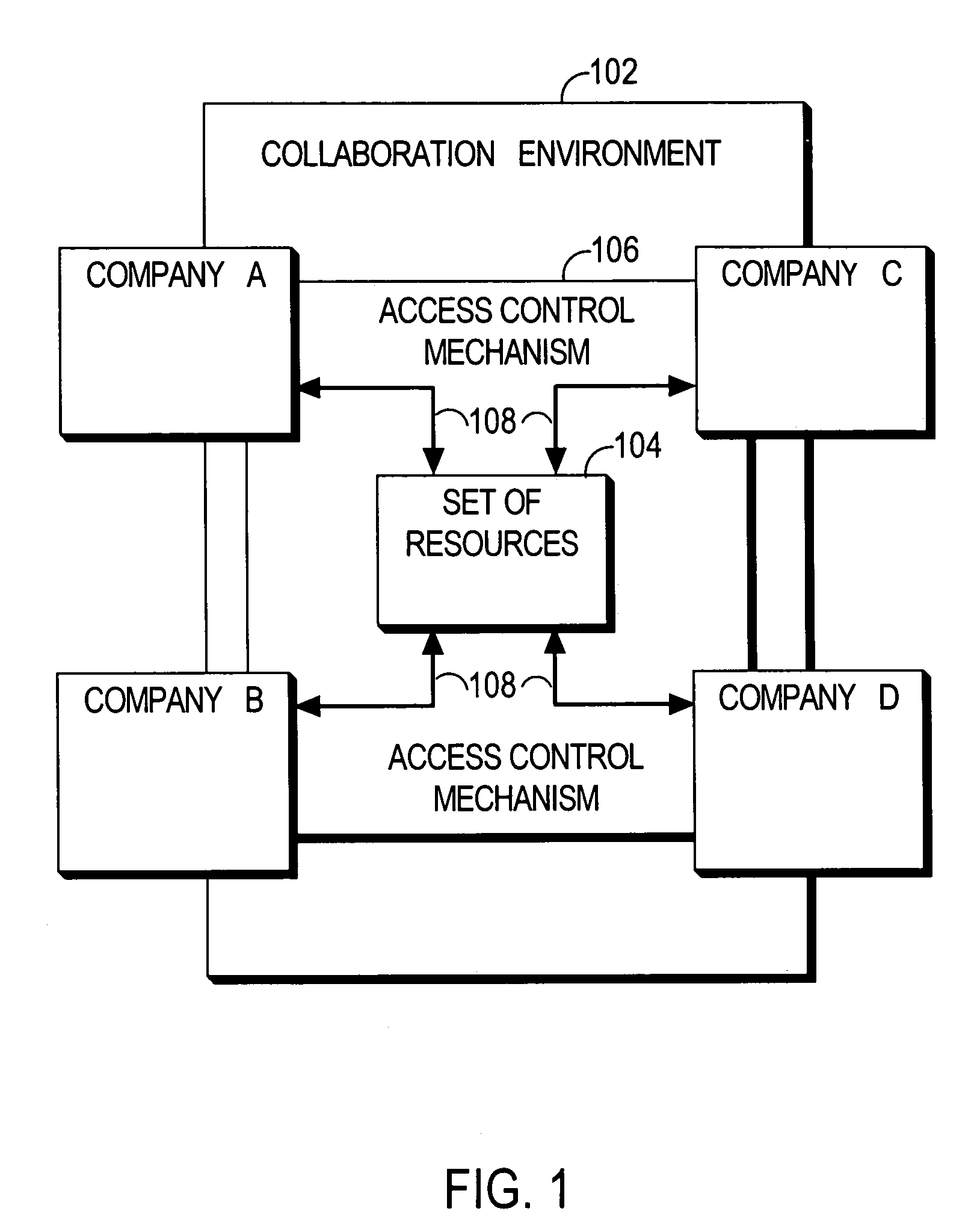
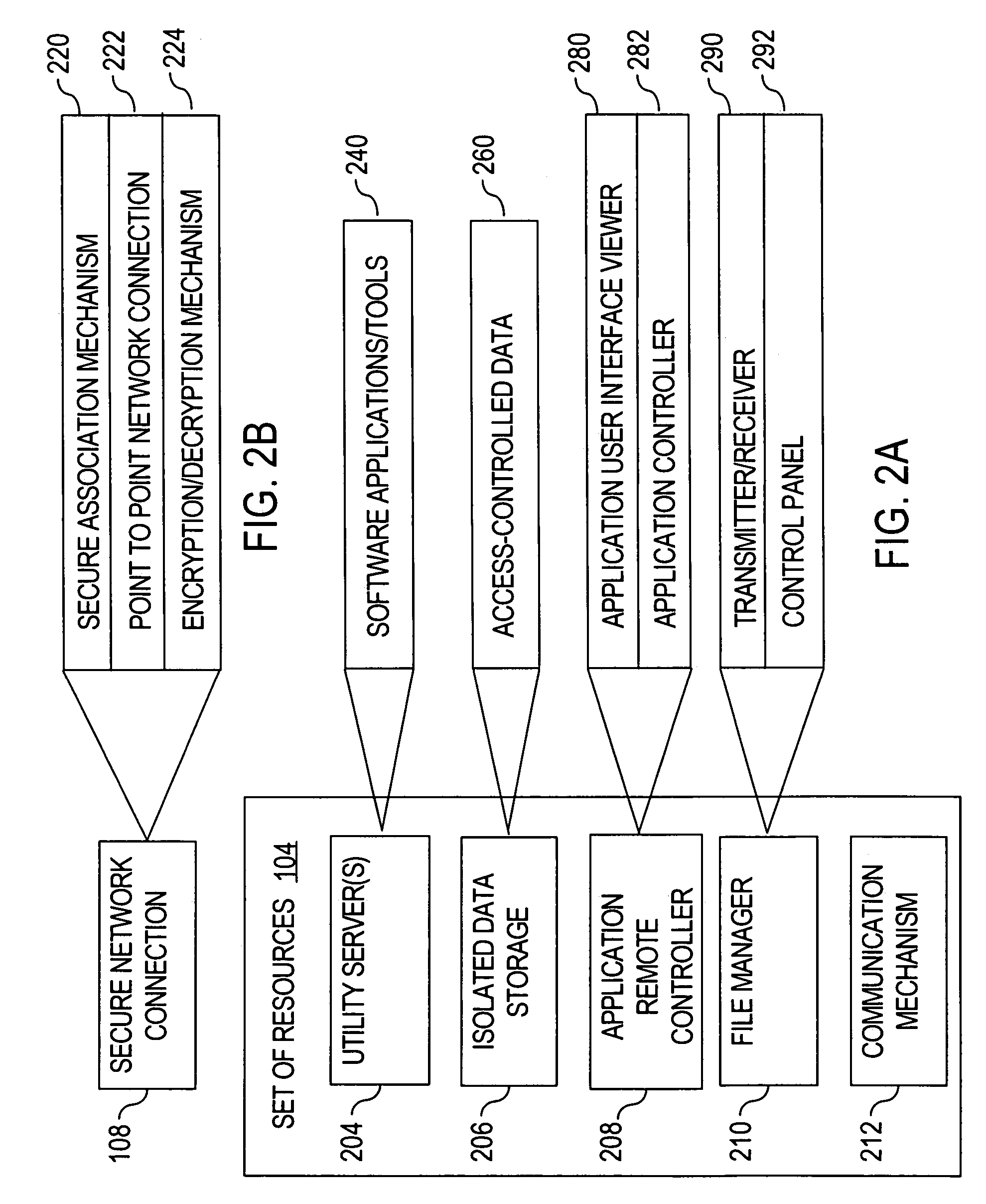
[0012]According to one aspect, a secure inter-company collaboration system includes a first and second set of utility servers maintained at a first and second company, respectively, and first and second sets of resources residing on the respective utility servers. Thus, for example without limitation, specialists from one company who have developed a particular design tool and who thus have expertise in the use of the design tool, can securely collaborate with project participants from another company who are using the design tool, via the secure collaboration system. If configured appropriately, the system allows the design tool and other applications to execute on either company's servers, while providing personnel from the other company with the capability to view and control the tool in real-time.

Problems solved by technology

For example, updating and maintaining a design environment has become more and more complex with diminishing feature sizes and the increase in the complexity of the designs.
None of the foregoing approaches have approximated the efficiency that teams working together physically can achieve.
For example, e-mail and FTP approaches are difficult to manage in view of the magnitude of common files associated with an IC engineering project, and are thus error-prone.
Additionally, complex problems are difficult to address and solve through e-mail and FTP communication alone because the problems are often embedded in the design environments, which often differ from site to site and company to company.
For another example, use of telnet technology allows one to run tools or applications on another site and to view text results, but does not support the graphical communication required in complex engineering projects.
Of course, co-location of engineering teams from different companies can provide the desired efficiencies, but it is often not feasible to co-locate personnel for geographical, cost, and logistical reasons.
Furthermore, co-location incurs the problems of constraining the engineers to working only on the joint project and of isolating them from the rest of their organization.
Electronic design automation (EDA) software applications that are often used in the design of ICs, at times encounter errors when executing within a specific scenario with specific external data.
Thus, the actual external data that caused the error is often needed to recreate the error in a separate instance of the application.
However, source code is typically proprietary and highly guarded intellectual property, which owners do not want to share with other parties.

Method used


Image

  • Isolated working chamber associated with a secure inter-company collaboration environment
  • Isolated working chamber associated with a secure inter-company collaboration environment
  • Isolated working chamber associated with a secure inter-company collaboration environment

Examples


example

Isolated System

[0116]FIG. 7 is a diagram illustrating an example architecture for an isolated system, such as isolated system 500 (FIG. 5), that is associated with a secure inter-company collaboration environment, such as environment 102 (FIG. 1), according to an embodiment of the invention. The specific architecture presented is for illustration purposes, thus the invention is not limited to the exact architecture depicted. FIG. 7 depicts a two-company collaboration environment 300, configured for Company A and Company B, and a single-company isolated system 700, configured for Company A only. Isolated system 700 is configured with different rules than environment 300. For example, different rules may apply with respect to governing and managing access, connectivity, file size, file systems, etc. A detailed description of the components that constitute a collaboration environment 300 is presented above in reference to FIG. 3.

[0117]Company A uses a client machine 302A (e.g., a conve...


PUM


Abstract

A system is described in which multiple companies can securely collaborate on a design or other project, while one company can still protect certain property, such as source code, from the other collaborating companies. The system includes an inter-company collaboration system that includes a set of resources residing on a set of one or more first utility servers maintained by a first company, an access control mechanism for controlling access to the set of resources, a first data storage mechanism, and a secure network connection between the set of utility servers and a second company. The system further includes an isolated system that includes a second set of servers, a second data storage mechanism that includes a first portion that contains data shared with the collaboration system and a second portion that contains data private to the isolated system, and a second access control mechanism to control access to the second set of servers to only individuals associated with one company.

Description

CROSS REFERENCE TO RELATED APPLICATION[0001]This is a continuation-in-part of U.S. patent application Ser. No. 10 / 164,831 filed on Jun. 6, 2002, now U.S. Pat. No. 7,143,136 which is incorporated by reference in its entirety for all purposes as if fully set forth herein.FIELD OF THE INVENTION[0002]The present invention relates generally to communications and, more specifically, to implementation of an isolated working chamber in association with a secure inter-company collaboration environment.BACKGROUND OF THE INVENTION[0003]Design and development projects naturally require a certain degree of collaboration among the projects' participants. Complex projects and projects in technological areas requiring high expertise, such as developing, maintaining and operating IC (integrated circuit) design environments or co-developing ICs, typically require a high degree of collaboration and communication. In cases in which more than one company work together on a project, the challenges are gr...

Claims


Application Information

Patent Timeline
IPC IPC(8): G06F15/173G06F15/16G06Q10/00
CPCG06Q10/025G06Q10/06G06Q10/10G06F21/125G06F11/362
Inventor CHIROGLAZOV, ANATOLI G.DRENAN, LAWRENCE A.
Owner CADENCE DESIGN SYST INC
Learn More