
Automated state estimation system for cluster tools and a method of operating the same

a cluster tool and automatic state estimation technology, applied in the field of manufacturing integrated circuits, can solve the problems of complex process tools, extreme cost, and the inability to handle multi-path cluster tools at an overall level, and achieve the effect of reducing the number of path cluster tools

Active Publication Date: 2009-06-09
FULLBRITE CAPITAL PARTNERS
View PDF5 Cites 9 Cited by
  • Summary
  • Abstract
  • Description
  • Claims
  • Application Information

AI Technical Summary

Benefits of technology

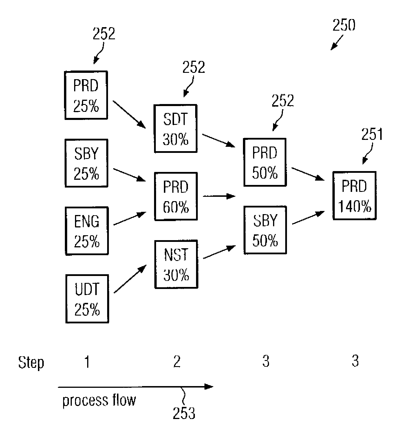
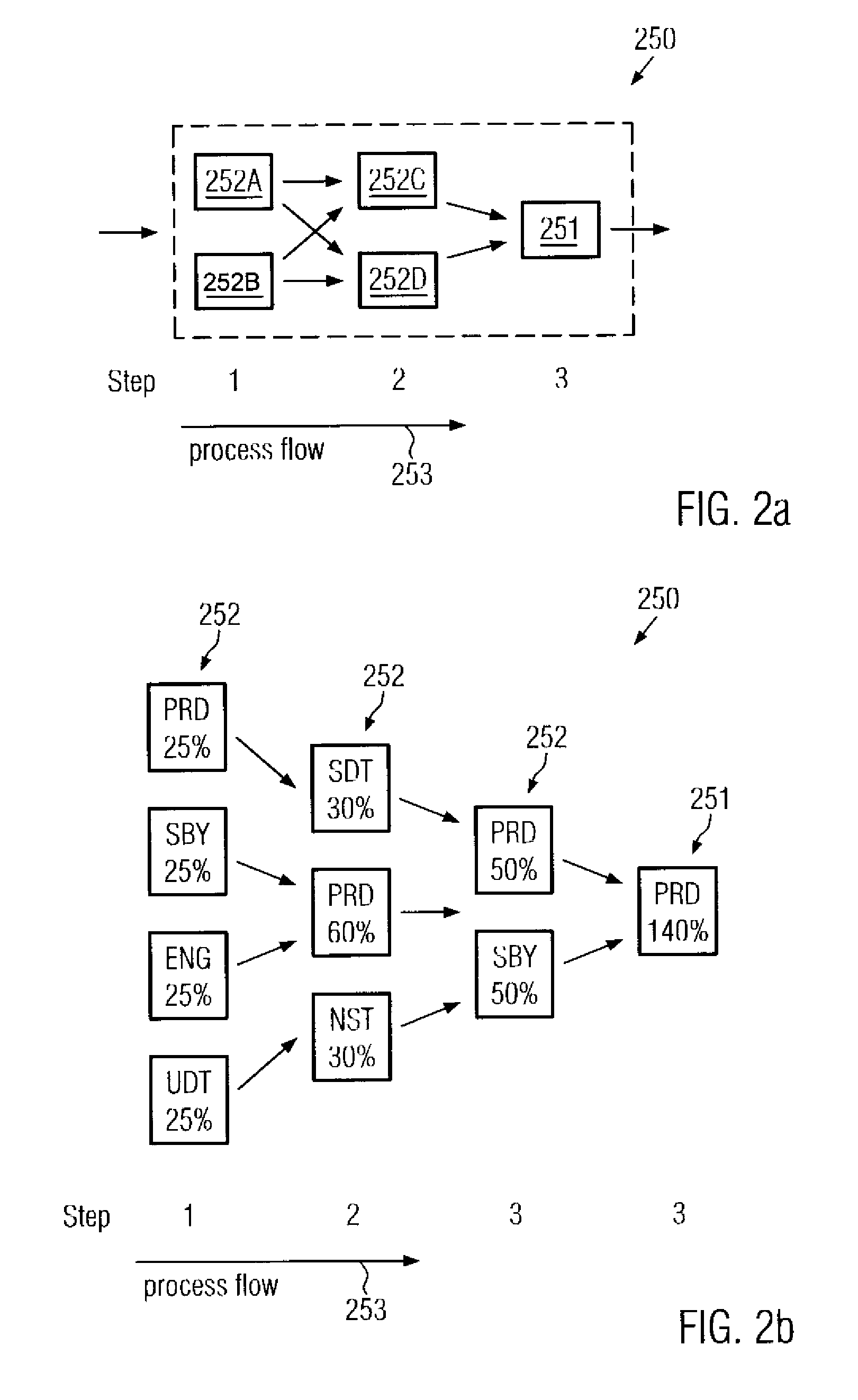
[0035]Generally, the present invention is directed to a technique that enables efficient measurement and assessment of cluster tool characteristics, such as reliability, availability and maintainability. on the basis of a plurality of different states of at least some of the entities comprising the respective cluster tool. For this purpose, “combined” states for the cluster tool as an entity may be defined, wherein the corresponding states of the individual entities may represent sub-states, the various contributions of which determine the total state of the cluster tool. In order to appropriately combine the individual sub-states into a total state, appropriate weighting or normalization factors may be established, which substantially determine the influence of specific sub-states on the total cluster tool state. In some illustrative embodiments, a hierarchy may be established for the plurality of sub-states, i.e., for the individual states each entity of the cluster tool may take on, in order to establish a corresponding ranking in which one state may overrule other states in a sequence of states within the cluster tool. Consequently, due to the combination of a plurality of sub-states, the total state of the cluster tool when considered as an entity may be monitored and measured in a more accurate and reliable fashion, thereby providing a reliable basis for determining other tool-specific metrics, wherein, in some illustrative embodiments, corresponding measurement values may be obtained that are immediately comparable with corresponding measurement results for single process tools, thereby addressing aspects with respect to measurement against availability commitments of suppliers and providing a basis for data enabling a statement with respect to tool capacity.

Problems solved by technology

The latter aspect is especially important, since, in modern semiconductor facilities, equipment is required which is extremely cost intensive and represents the dominant part of the total production costs.
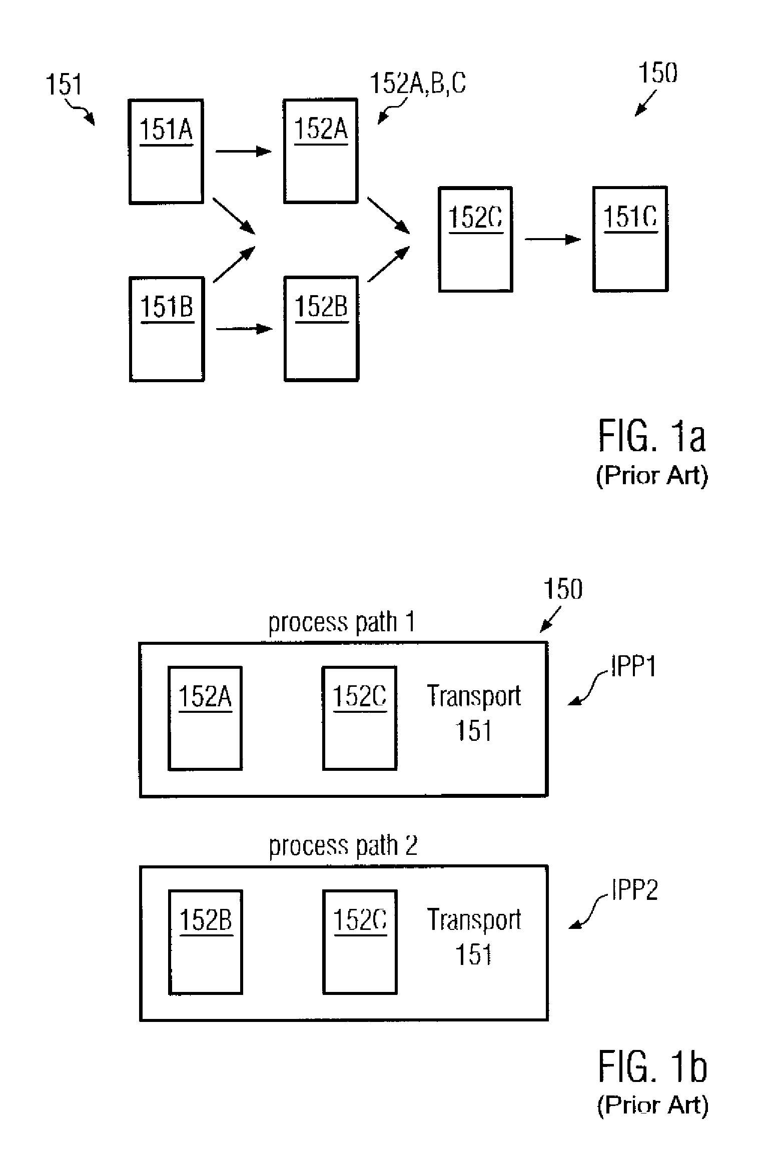
Recently, process tools have become more complex in that a process tool may include a plurality of functional modules or entities, referred to as cluster or cluster tool, which may operate in a parallel and / or sequential manner such that a product arriving at the cluster tool may be operated therein in a plurality of process paths, depending on the process recipe and the current tool state.
As previously stated, the states defined within the E10 standard may not allow handling multi-path cluster tools at an overall level but may be applied to the individual tool entities.
Consequently, reliability, for instance in the form of mean time between failure (MTBF), availability, for instance in the form of operational uptime, and maintainability, for instance in the form of mean time to repair (MTTR), for the various tool entities may be calculated, wherein these metrics, however, do not provide a metric for the multi-path cluster tool as an entity itself.
Simultaneously, although being in a productive state, a failure may exist and may require equipment maintenance, thereby rendering the present definitions of uptime and downtime less effective for the cluster tool 150.
The transport system 151 may have one failure, thereby resulting in an MTBF of 140 hours.
In the above-described measurement technique for evaluating the state of a cluster tool, some issues may arise when applying the above-specified technique to the production environment including a variety of complex cluster tools, since the measurement results received by the above-specified technique may result in a reduced accuracy and thus confidence for the assessment of respective cluster tool states.
For example, in the above-specified technique for assessing the tool state of a cluster tool in its entirety, the reconfiguration of a relatively purely performing cluster tool by adding high reliable entities, such as pass through chambers and the like, would significantly increase the MTBF value, thereby indicating an increased reliability, which may, however, be unrealistic.
As a consequence, the measurement of cluster tool characteristics, such as reliability, availability and maintainability according to conventional techniques may yield less reliable results, thereby significantly affecting production control in a semiconductor facility.

Method used


Image

  • Automated state estimation system for cluster tools and a method of operating the same
  • Automated state estimation system for cluster tools and a method of operating the same
  • Automated state estimation system for cluster tools and a method of operating the same

Examples


Embodiment Construction

[0049]Illustrative embodiments of the invention are described below. In the interest of clarity, not all features of an actual implementation are described in this specification. It will of course be appreciated that in the development of any such actual embodiment, numerous implementation-specific decisions must be made to achieve the developers' specific goals, such as compliance with system-related and business-related constraints, which will vary from one implementation to another. Moreover, it will be appreciated that such a development effort might be complex and time-consuming, but would nevertheless be a routine undertaking for those of ordinary skill in the art having the benefit of this disclosure.

[0050]The present invention will now be described with reference to the attached figures. Various structures, systems and devices are schematically depicted in the drawings for purposes of explanation only and so as to not obscure the present invention with details that are well ...


PUM


Abstract

By using weighted entity states for representing a state of a cluster tool, a highly efficient technique for the measurement and monitoring of cluster tool characteristics, such as reliability, availability and maintainability, is provided. For example, individual entities of the cluster tool may be weighted according to their capacity and corresponding entity states may be ranked in accordance with a predefined hierarchy structure, thereby enabling an efficient combination of weighted entity states so as to represent the cluster tool state.

Description

BACKGROUND OF THE INVENTION[0001]1. Field of the Invention[0002]Generally, the present invention relates to the field of fabricating integrated circuits, and, more particularly, to monitoring and measuring process tool characteristics of a process tool used for the fabrication of semiconductor devices or other microstructures.[0003]2. Description of the Related Art[0004]Today's global market forces manufacturers of mass products to offer high quality products at a low price. It is thus important to improve yield and process efficiency to minimize production costs. This holds especially true in the field of microstructure fabrication, for instance for manufacturing semiconductor devices, since, in this field, it is essential to combine cutting-edge technology with mass production techniques. It is, therefore, the goal of manufacturers of semiconductors, or generally of microstructures, to reduce the consumption of raw materials and consumables while at the same time improving process...

Claims


Application Information

Patent Timeline
Patent Type & Authority Patents(United States)
IPC IPC(8): G06F19/00G06Q10/00
CPCG05B23/0251G05B19/4187G06Q10/06Y02P80/40Y02P90/02Y02P90/80G06F15/00G06Q10/103G06Q50/04
Inventor DIERKS, ULRICHSCHUMACHER, HARDY
Owner FULLBRITE CAPITAL PARTNERS
Learn More