
Method for setting parameters of a vision detector using production line information

a production line and parameter setting technology, applied in the field of automatic detection and inspection of objects, can solve the problems of limitations of machine vision systems, and inability to make correct decisions

Active Publication Date: 2009-06-09
COGNEX TECH & INVESTMENT
View PDF43 Cites 11 Cited by
  • Summary
  • Abstract
  • Description
  • Claims
  • Application Information

AI Technical Summary

Benefits of technology

The invention provides methods and systems for setting the shutter time and video gain parameters of an imager that captures images of a production line. The shutter time controls the blurring of captured images due to motion, while the video gain controls the signal-to-noise ratio and brightness of the image. The invention recognizes that there is a tradeoff between blurring and fidelity, and provides methods for setting the shutter time and video gain to achieve the desired brightness and fidelity. The invention also provides methods for estimating the apparent line speed and motion shutter time, which can be used to set the shutter time and video gain parameters. Overall, the invention improves the performance of the imager in capturing images of a production line.

Problems solved by technology

Machine vision systems have limitations that arise because they make decisions based on a single image of each object, located in a single position in the field of view (each object may be located in a different and unpredictable position, but for each object there is only one such position on which a decision is based).
The use of only a single perspective often leads to incorrect decisions.
It has long been observed, for example, that a change in perspective of as little as a single pixel can in some cases change an incorrect decision to a correct one.
Machine vision systems have additional limitations arising from their use of a trigger signal.
The need for a trigger signal makes the setup more complex—a photodetector must be mounted and adjusted, or software must be written for a PLC or computer to provide an appropriate message.
Furthermore, photodetectors can only respond to a change in light intensity reflected from an object or transmitted along a path.
In some cases, such a condition may not be sufficient to reliably detect when an object has entered the field of view.
Self-triggering is rarely used in practice due to several limitations:The vision systems respond too slowly for self-triggering to work at common production speeds;The methods provided to detect when an object is present are not sufficient in many cases; andThe vision systems do not provide useful output signals that are synchronized to a specific, repeatable position of the object along the production line, signals that are typically provided by the photodetector that acts as a trigger and needed by a PLC or handling mechanism to take action based on the vision system's decision.
Many of the limitations of machine vision systems arise in part because they operate too slowly to capture and analyze multiple perspectives of objects in motion, and too slowly to react to events happening in the field of view.
These frames may not be strictly consecutive, however, because as the object passes through the field of view there may be some viewing perspectives, or other conditions, for which the evidence that the object is located in the field of view is not sufficient.
Note that doing so is at least in part a matter of human judgment—there is no formula or set of formulas that gives optimal results in all situations, partly because most situations cannot be foreseen and partly because setting the parameters involves engineering tradeoffs where there is no clear optimal solution.
It has long been observed that the people who install and configure optoelectronic inspection devices in factories are often of considerably less than ordinary skill in the art of the Vision Detector Method and Apparatus.
These people will know production conditions related to their own expertise, such as the physical speed of the line, the physical size of the field of view (i.e. inches, not pixels), and the production rate, but may not know how to relate those conditions to suitable values for the operating parameters of a vision detector.

Method used


Image

  • Method for setting parameters of a vision detector using production line information
  • Method for setting parameters of a vision detector using production line information
  • Method for setting parameters of a vision detector using production line information

Examples


Embodiment Construction

Basic Operation of The Vision Detector Method and Apparatus

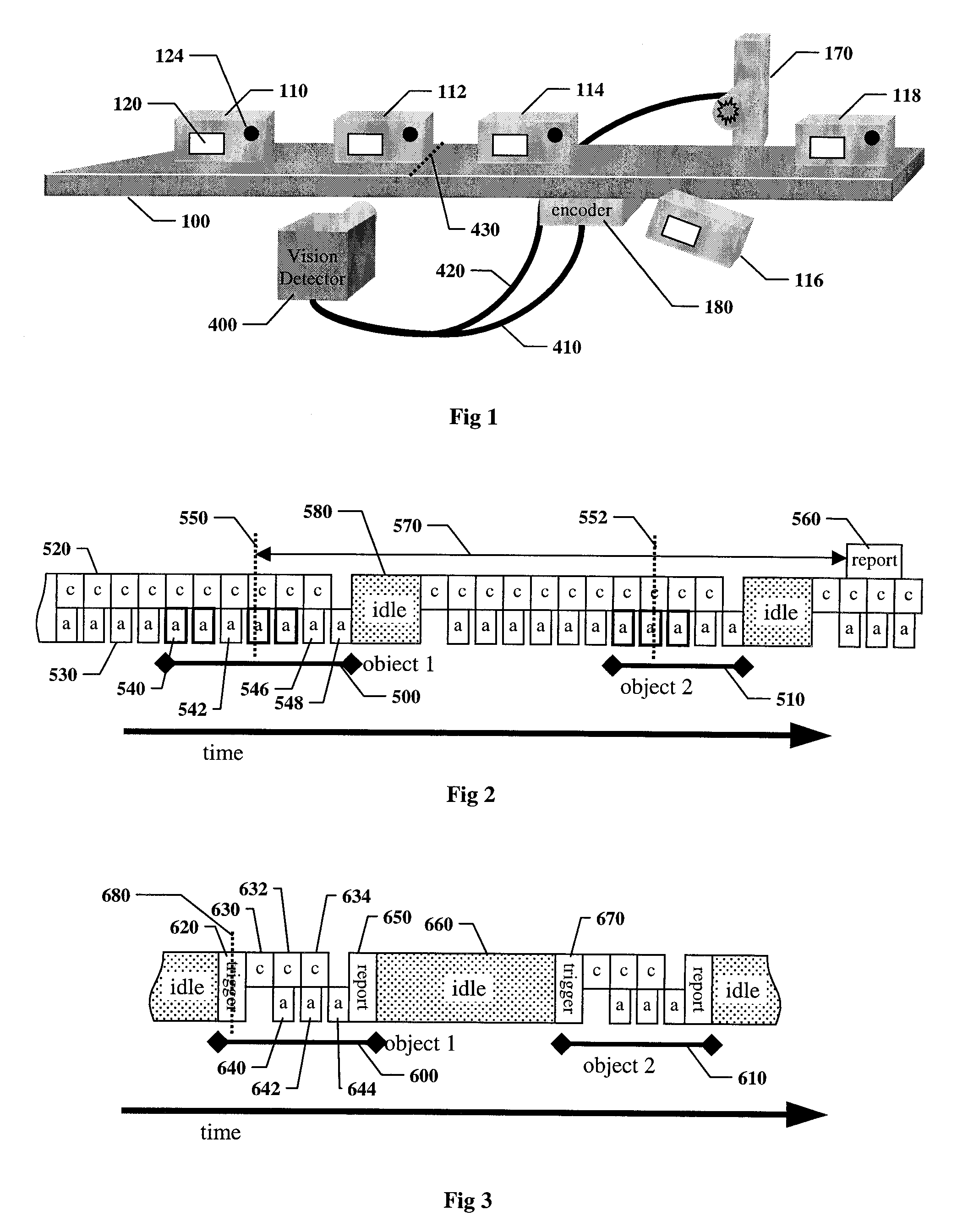
[0096]FIG. 1 shows an illustrative embodiment of a vision detector according to the Vision Detector Method and Apparatus, inspecting objects on a production line. A conveyer 100 transports objects to cause relative movement between the objects and the field of view of vision detector 400. Objects 110, 112, 114, 116, and 118 move left to right on a conveyer 100. Each object is expected to contain certain features, for example a label 120 and a hole 124. Objects incorrectly manufactured may be missing one or more features, or may have unintended features; for example, object 116 is missing the hole. On many production lines motion of the conveyer is tracked by a shaft encoder 180. A vision detector 400 detects the presence of an object by visual appearance and inspects it based on appropriate inspection criteria. If an object is defective, the vision detector sends signal 420 to reject actuator 170 to remove the object from th...


PUM


Abstract

Disclosed are systems and methods for setting various operating parameters of a vision detector from production line information that can be supplied by a manufacturing technician who is not skilled in the art of the invention. These operating parameters include shutter time, video gain, idle time, frame count, and locator search range. The production line information includes line speed, field of view size, direction of motion, and object spacing.

Description

RELATED APPLICATION[0001]This application is a continuation-in-part of co-pending U.S. patent application Ser. No. 10 / 865,155, entitled METHOD AND APPARATUS FOR VISUAL DETECTION AND INSPECTION OF OBJECTS, by William M. Silver, filed Jun. 9, 2004, the teachings of which are expressly incorporated herein by reference, and referred to herein as the “Vision Detector Method and Apparatus”.BACKGROUND OF THE INVENTION[0002]1. Field of the Invention[0003]The invention relates to automated detection and inspection of objects being manufactured on a production line, and more particularly to the related fields of industrial machine vision and automated image analysis.[0004]2. Description of the Related Art[0005]Industrial manufacturing relies on automatic inspection of objects being manufactured. One form of automatic inspection that has been in common use for decades is based on optoelectronic technologies that use electromagnetic energy, usually infrared or visible light, photoelectric senso...

Claims


Application Information

Patent Timeline
Patent Type & Authority Patents(United States)
IPC IPC(8): G06K9/00G03B7/087G03B7/097H04N5/222H04N5/225H04N5/232H04N9/04
CPCG03B7/087G03B7/097H04N5/23216H04N23/62
Inventor MIRTICH, BRIAN V.SILVER, WILLIAM M.
Owner COGNEX TECH & INVESTMENT
Learn More