Electronic apparatus, connecting mounting for electronic apparatus, and connecting system including electronic apparatus and connecting mounting
a technology for connecting mounting and electronic equipment, which is applied in the direction of television system, coupling device connection, instruments, etc., can solve the problems of user being required to do troublesome preparation operation and troublesome manipulation
- Summary
- Abstract
- Description
- Claims
- Application Information
AI Technical Summary
Benefits of technology
Problems solved by technology
Method used
Image
Examples
first embodiment
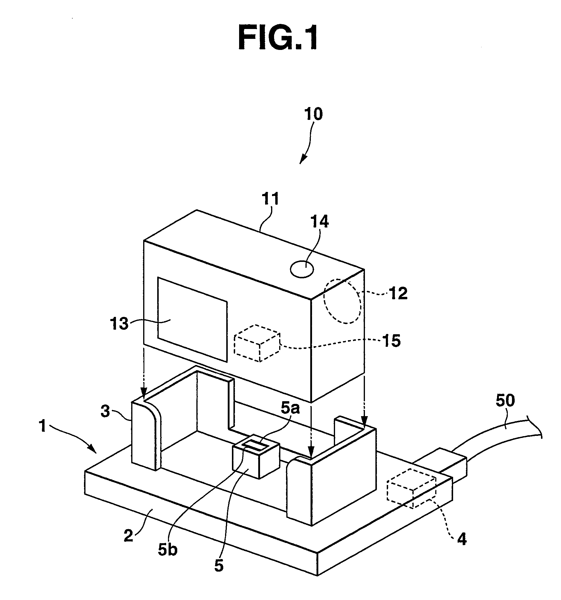
[0032]FIG. 1 is a view illustrating a perspective external view of a connecting system according to a first embodiment of the invention. The connecting system includes a connecting mounting or a cradle 1 and a digital camera 10 which is mounted on the cradle 1. When mounted on or held by the cradle 1, the digital camera 10 is electrically connected to a personal computer (PC) through the cradle 1 to exchange data therewith.
[0033]The cradle 1 has a base 2 and a holding unit 3 mounted on the base 2. The holding unit 3 of the cradle 1 has a structure for slightly tilting the digital camera 10 back to hold therein. The base 2 of the cradle 1 has a first connector 4 in its rear side and a second connector 5 on its top surface, which projects from the top surface and surrounded by the holding unit 3. A cable 50 connected with the personal computer at its one end (not shown) is connected to the first connector 4 of the cradle 1. Terminals of the first connector 4 are connected to those of ...
second embodiment
[0052]FIG. 4 is a view illustrating a perspective external view of a connecting system according to a second embodiment of the invention. The connecting system includes a connecting mounting or a cradle 101 and a digital camera 10 which is mounted on the cradle 1. When held by or mounted on the cradle 1, the digital camera 10 is electrically connected to a personal computer (PC) through the cradle 101 to exchange data therewith.
[0053]The cradle 101 has a base 102 in the top of which a round opening 102a is formed, and a rotating round table 106 which is rotatably mounted within the round opening 102a. The rotatable round table 106 is a moving member of the connecting system of the invention, and on the top surface of the rotatable round table 102 is provided a holding unit 103. The rotatable table 106 is allowed to rotate in a horizontal plane parallel to the base 102 by more than 180 degrees, and has a projection 106a on its peripheral surface.
[0054]A first connector 104 is provide...
third embodiment
[0062]FIG. 6 is a view illustrating a perspective external view of a connecting system according to a third embodiment of the invention. The connecting system includes a connecting mounting or a cradle 201 and a digital camera 210 which is mounted on the cradle 201. When held by or mounted on the cradle 201, the digital camera 210 is electrically connected to a personal computer (PC) through the cradle 201 to exchange data therewith.
[0063]The cradle 201 in the third embodiment is of a substantially same structure as the first embodiment, but is different from the first embodiment in that a second connector 205 provided within the holding unit 3 has only one set of data communication terminals.
[0064]The digital camera 210 in the third embodiment is different from those of the first and the second embodiments. The digital camera 210 has a movable portion 211 on a side wall of the camera body 11. More specifically, the movable portion 211 is rotatably mounted on the side wall about an ...
PUM
 Abstract
Description
Claims
Application Information
 - Generate Ideas
- Intellectual Property
- Life Sciences
- Materials
- Tech Scout
- Unparalleled Data Quality
- Higher Quality Content
- 60% Fewer Hallucinations
Browse by: Latest US Patents, China's latest patents, Technical Efficacy Thesaurus, Application Domain, Technology Topic, Popular Technical Reports.
© 2025 PatSnap. All rights reserved.Legal|Privacy policy|Modern Slavery Act Transparency Statement|Sitemap|About US| Contact US: help@patsnap.com


