
Method of manufacturing electronic device capable of controlling threshold voltage and ion implanter controller and system that perform the method

a technology of electronic devices and threshold voltages, applied in the direction of semiconductor/solid-state device testing/measurement, instruments, therapy, etc., can solve the problems of insufficient compensation, affecting inability to compensate for a variation in the effective length of the channel, so as to achieve effective compensation for threshold voltage variations

Active Publication Date: 2009-05-26
SAMSUNG ELECTRONICS CO LTD
View PDF12 Cites 2 Cited by
  • Summary
  • Abstract
  • Description
  • Claims
  • Application Information

AI Technical Summary

Benefits of technology

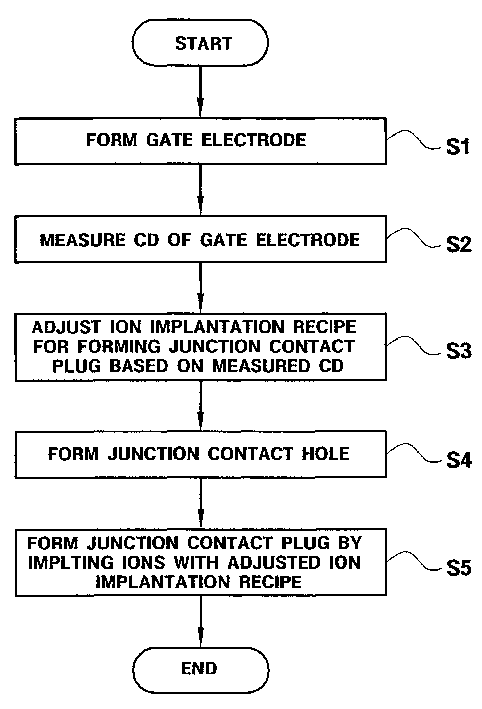
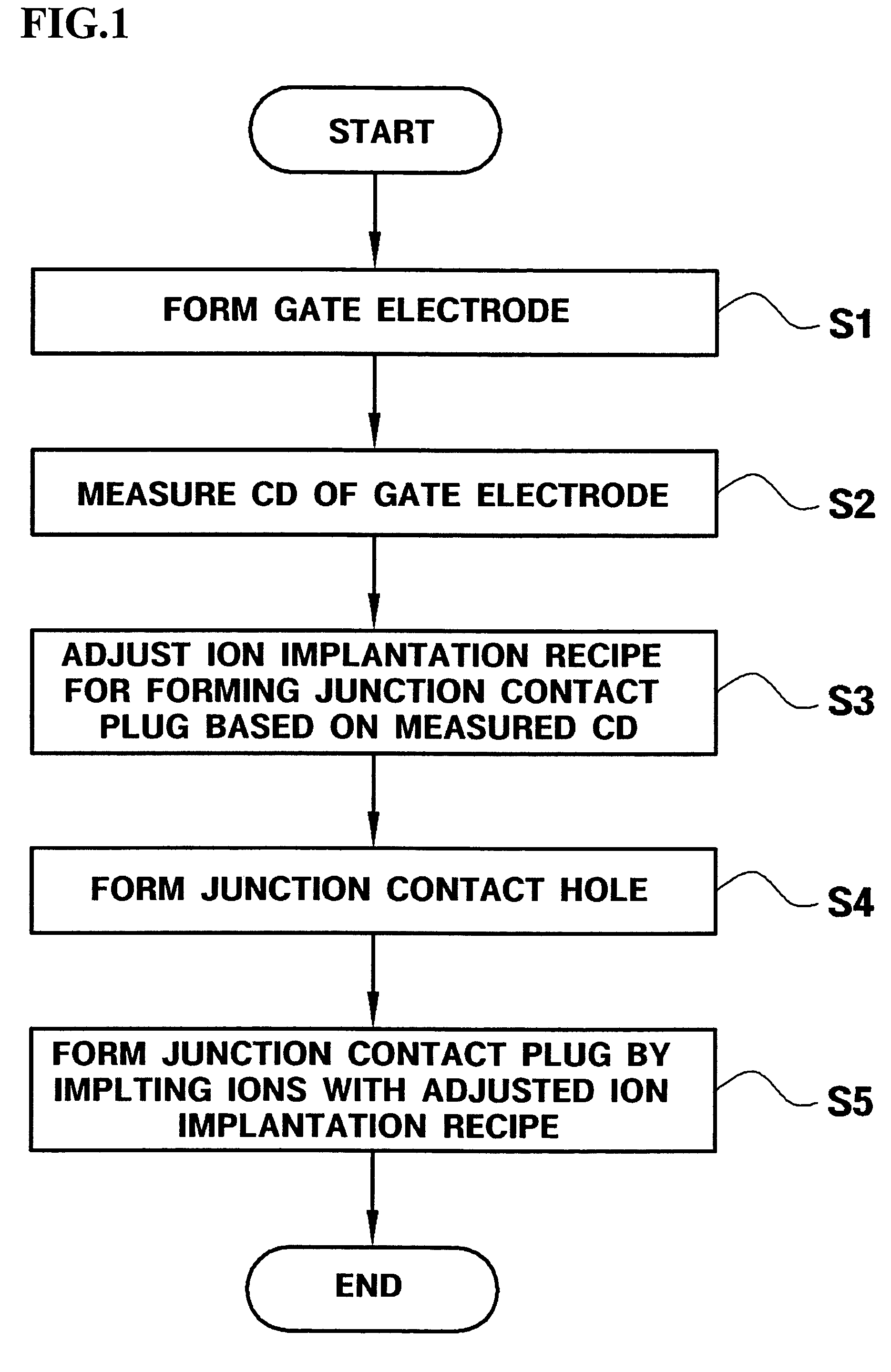
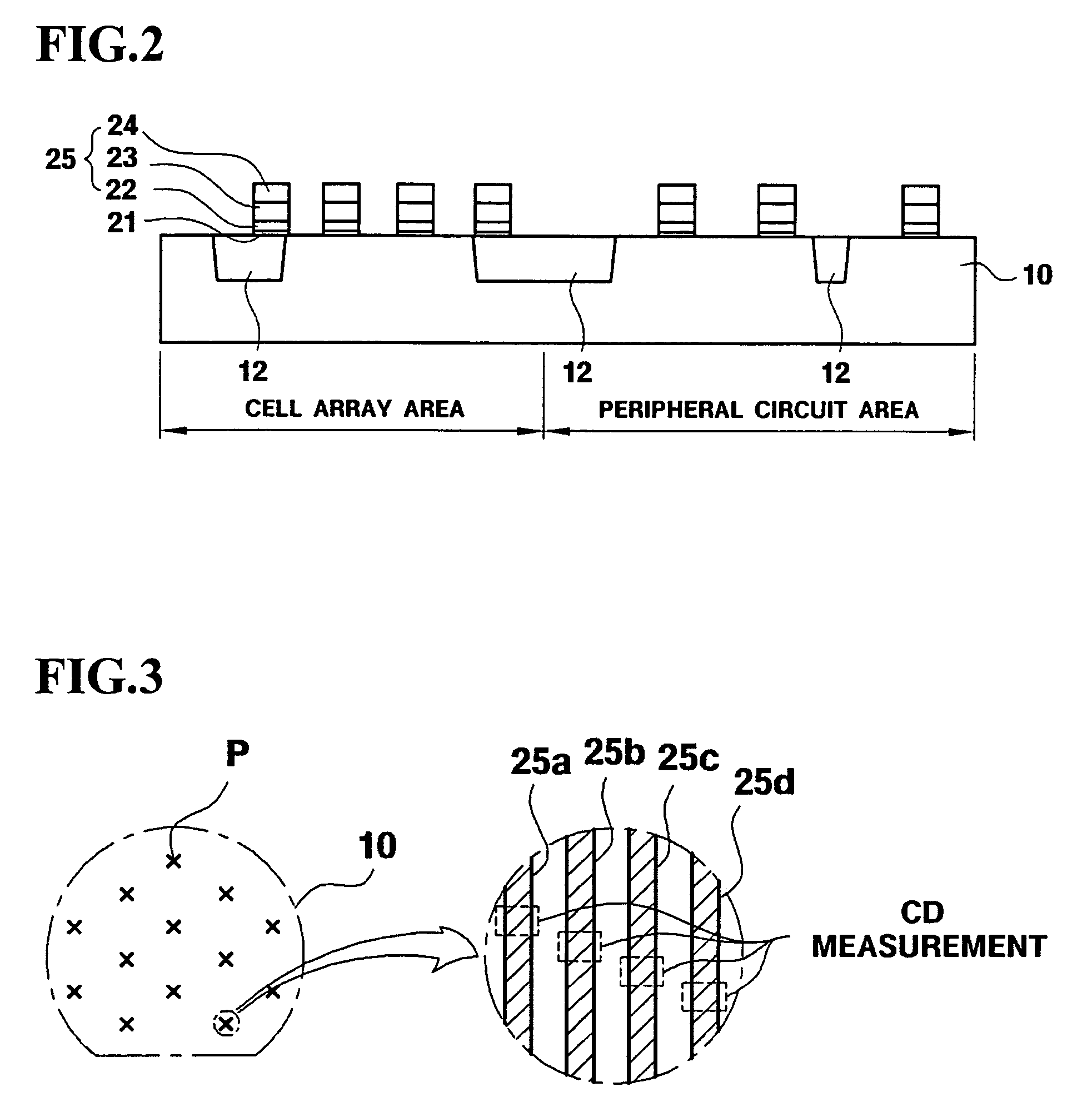
The present invention provides a method and system for manufacturing an electronic device that can effectively compensate for threshold voltage variations caused by critical dimension variations. This is achieved by measuring the CD of a gate electrode on a wafer, adjusting an ion implantation recipe for forming a junction contact plug of a transistor based on the measured CD, and performing ion implantation using the adjusted recipe. The technical effect is to improve the stability and reliability of electronic devices manufactured using this method and system.

Problems solved by technology

However, such conventional methods only compensate for a variation in the effective length of a channel that occurs due to the variation of the CD of the gate electrode.
Therefore, it is impossible to sufficiently compensate for threshold voltage variations caused by the variation of the CD of the gate electrode by simply adjusting the ion implantation recipe, which only affects the effective length of the channel.
Accordingly, it is still impossible to prevent static and / or dynamic refresh failures caused by the variation of the CD of the gate electrode from occurring.

Method used


Image

  • Method of manufacturing electronic device capable of controlling threshold voltage and ion implanter controller and system that perform the method
  • Method of manufacturing electronic device capable of controlling threshold voltage and ion implanter controller and system that perform the method
  • Method of manufacturing electronic device capable of controlling threshold voltage and ion implanter controller and system that perform the method

Examples


Embodiment Construction

[0029]The present invention now will be described more fully with reference to the accompanying drawings, in which preferred embodiments of the invention are shown. This invention may, however, be embodied in many different forms and should not be construed as being limited to the embodiments set forth herein; rather, these embodiments are provided so that this disclosure will be thorough and complete, and will fully convey the concept of the invention to those skilled in the art. The spirit and scope of the invention is defined by the appended claims. In the drawings, the same reference numerals denote the same member. Throughout the specification, the terms “first conductivity type” and “second conductivity type” denote opposite conductivity types, like n- and p-type. The respective illustrative embodiments of the invention encompass complementary examples thereof. In several embodiments of the invention, well known methods involving well-known circuits, components, techniques, et...


PUM

PropertyMeasurementUnit
temperatureaaaaaaaaaa
diameteraaaaaaaaaa

Abstract

A method of manufacturing an electronic device, which can obtain sufficient manufacturing margins and reduce a defect rate by compensating for a threshold voltage variation caused by the variation of a critical dimension (CD) of a gate electrode. An ion implanter controller and an ion implantation system perform the method. In the method, an ion implantation recipe for forming a junction contact plug of a transistor formed on the wafer is adjusted based on the measured CD. Then, ions are implanted into the wafer by using the adjusted ion implantation recipe. All defects that may occur in the transistor during previous manufacturing steps can be repaired after the transistor is formed, thus enhancing manufacturing margins.

Description

[0001]This application claims priority from Korean Patent Application No. 10-2004-0008059 filed on Feb. 6, 2004 with the Korean Intellectual Property Office, the disclosure of which is incorporated herein in its entirety by reference.BACKGROUND OF THE INVENTION[0002]1. Field of the Invention[0003]The present invention relates to a method of manufacturing an electronic device capable of controlling a threshold voltage, and an ion implanter controller and system that perform the method.[0004]2. Description of the Related Art[0005]Generally, ion implantation for manufacturing an electronic device is performed according to a predetermined ion implantation recipe composed of various ion implantation variables. But the various ion implantation variables are typically fixed regardless of a variation in the critical dimension (CD) of a gate electrode that has already been formed before the ion implantation. However, the variation of the CD of the gate electrode is one of the most critical f...

Claims


Application Information

Patent Timeline
Patent Type & Authority Patents(United States)
IPC IPC(8): H01L21/66H01J37/317A61N5/00B05C11/00G01R31/26G21G5/00G21K5/10H01J37/08H01L21/02H01L21/265H01L21/336H01L21/425H01L29/78
CPCH01L22/20H01J2237/30455H01J2237/31701H01L29/6659H01L2924/0002H01L2924/00F16L59/00C08J7/04C08J2367/00
Inventor LEE, YOUNG-HOLEE, SUN-YONGBAEK, DOO-HEUNPARK, TAE-HOON
Owner SAMSUNG ELECTRONICS CO LTD
Learn More