
Pneumatic tire with tread including circumferential grooves having inclined ridges or recesses

a technology of pneumatic tires and circumferential grooves, which is applied in the direction of non-skid devices, vehicle components, transportation and packaging, etc., can solve the problems of insufficient capability of preventing hydroplaning and inability to obtain positive discharge of water, so as to achieve the effect of facilitating discharge action and dramatically improving the ability to prevent hydroplaning

Inactive Publication Date: 2009-05-26
THE YOKOHAMA RUBBER CO LTD
View PDF23 Cites 12 Cited by
  • Summary
  • Abstract
  • Description
  • Claims
  • Application Information

AI Technical Summary

Benefits of technology

[0004]An object of the present invention is to provide a pneumatic tire capable of positively discharging water having flowed into a groove extending in the tire circumferential direction and enhancing the capability of preventing hydroplaning.
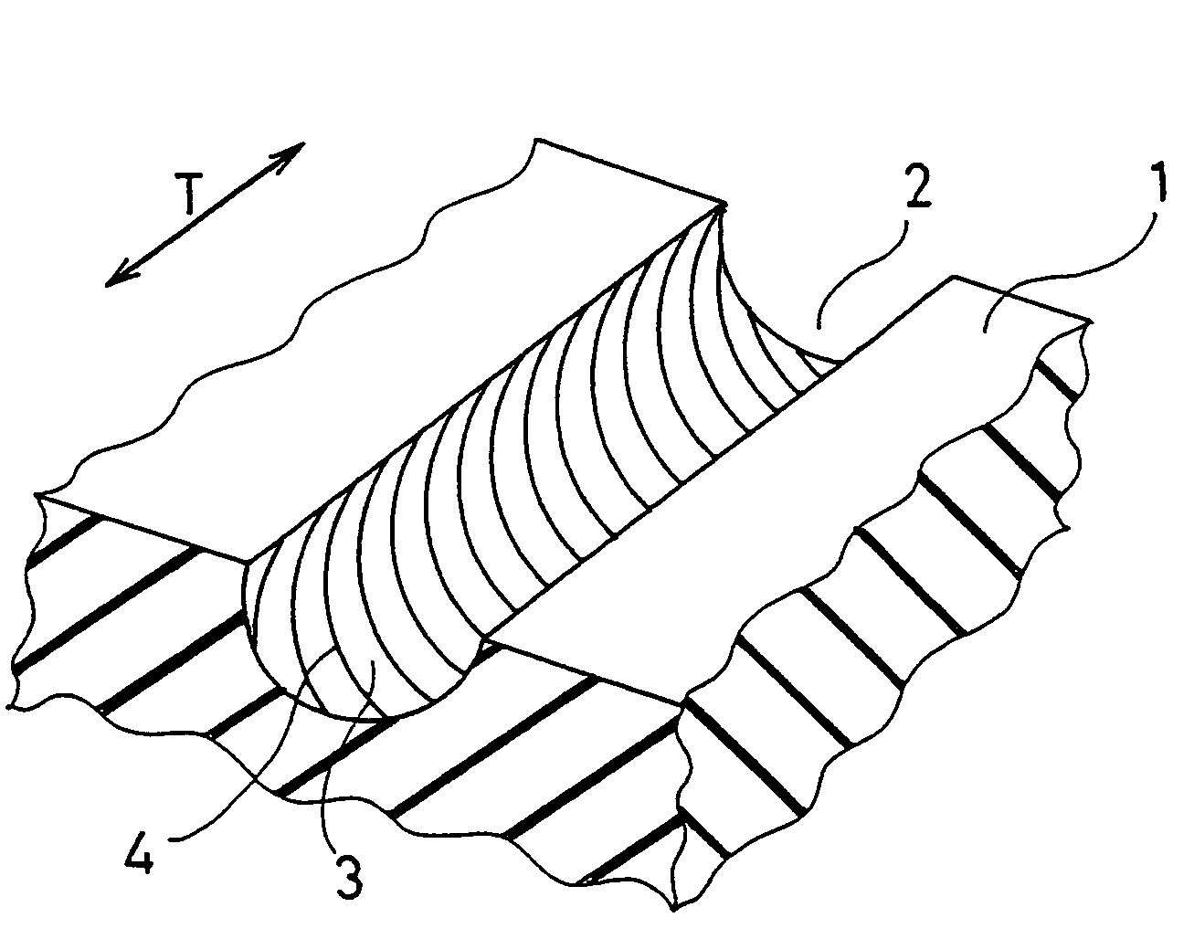
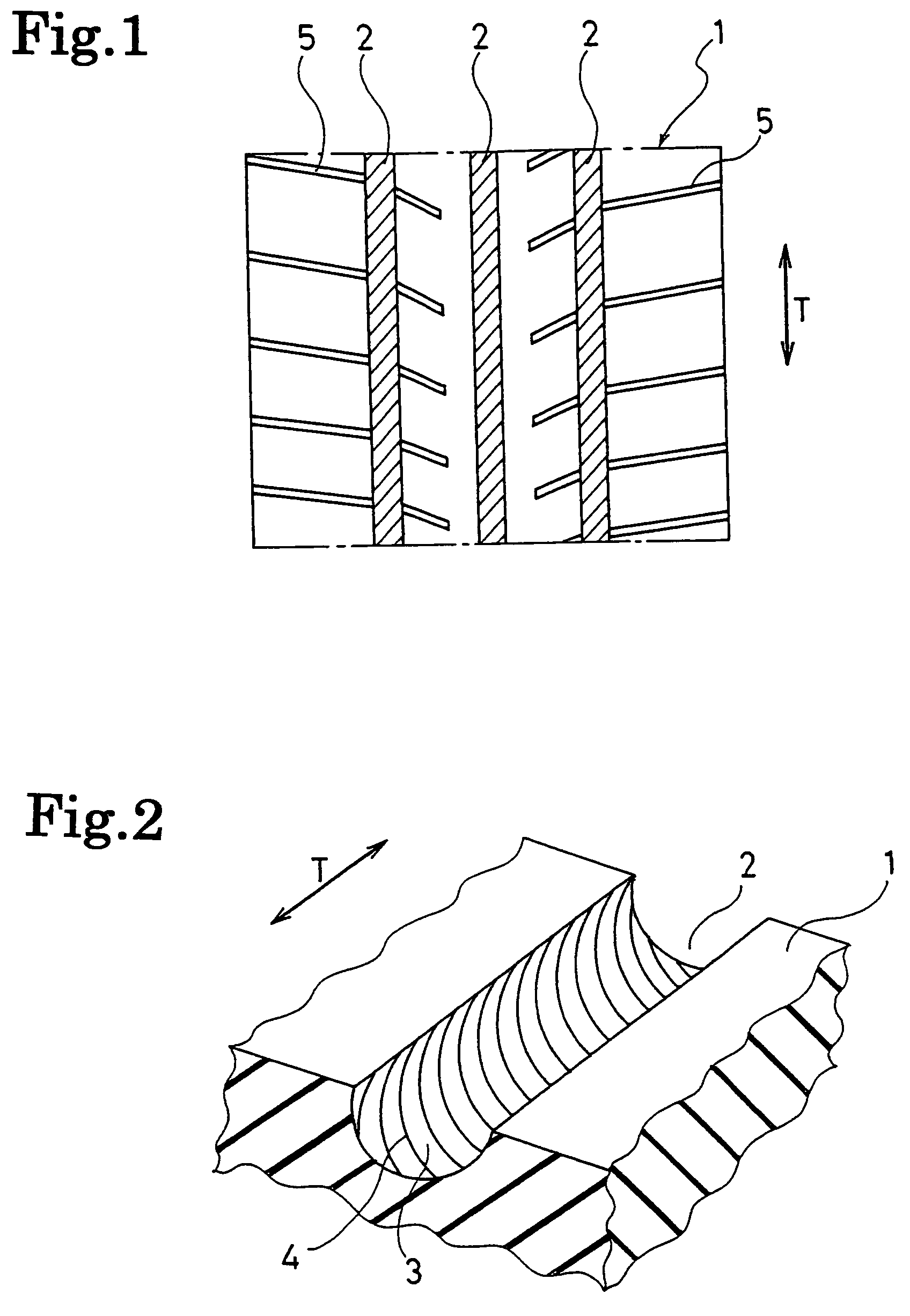
[0007]Accordingly, water having flowed into the groove flows along the line portions, which are formed in the wall face of the groove and spirally arranged, and forms a vortex flow. The water is then accelerated to progress within the groove and discharged to the exterior. Since water on a road is a continuum, a negative pressure is created within the groove according to the amount of water accelerated and discharged. Thus, a larger amount of water is drawn into the groove, and a larger amount of water is then discharged. Moreover, since the water progressing within the groove while forming the vortex flow moves toward the center position of the groove space while swirling, thereby the contact resistance between water and the wall face of the groove is significantly reduced, and the discharging action is assisted as a result. The capability of preventing hydroplaning can be therefore dramatically improved.

Problems solved by technology

However, it is not possible to obtain an effect of positively discharging water having flowed into the groove to the exterior.
Accordingly, the capability of preventing hydroplaning has not necessarily been sufficient.

Method used


Image

  • Pneumatic tire with tread including circumferential grooves having inclined ridges or recesses
  • Pneumatic tire with tread including circumferential grooves having inclined ridges or recesses
  • Pneumatic tire with tread including circumferential grooves having inclined ridges or recesses

Examples


examples

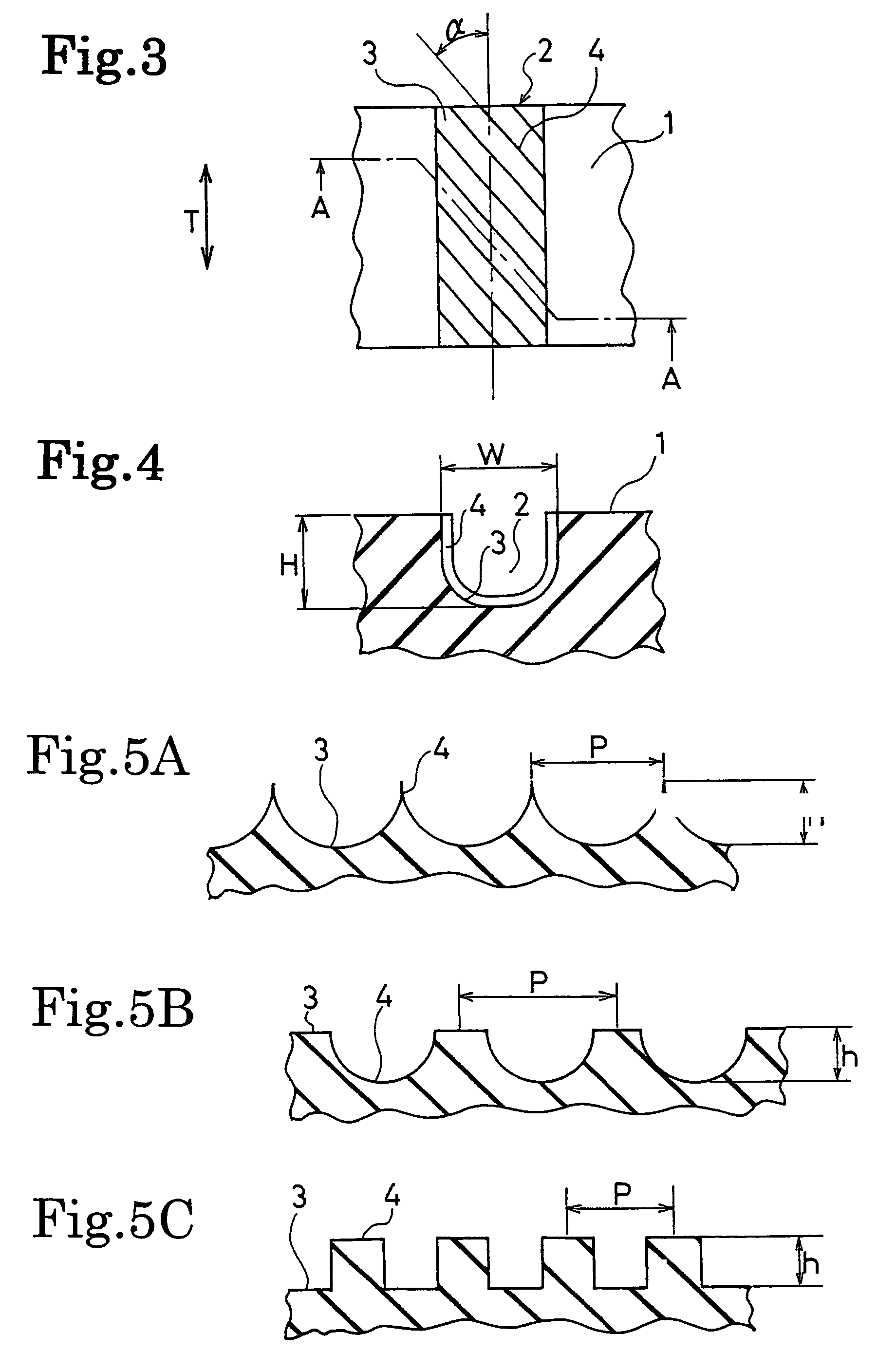
[0024]The pneumatic tires (Examples 1 to 5) of the present invention were fabricated as follows. In pneumatic tires (size: 205 / 60R15) each having the block pattern of FIG. 1, the line portions were provided in the wall face of the grooves extending in the tire circumferential direction, and the inclined angle a, height h, pitch interval P thereof were varied as shown in Table 1. For comparison, a conventional tire (Conventional Example) which was not provided with the line portions in the wall face of the grooves extending in the tire circumferential direction was fabricated. The grooves provided with the line portions had a groove width of 10 mm and a groove depth of 8 mm.

[0025]Each of these test tires was mounted on a domestically-produced car of 2.0 liter displacement and subjected to a hydroplaning test in straight running. In this hydroplaning test in straight running, the car was driven on a straight road provided with a pool having a water depth of 10 mm. The speed at which t...


PUM


Abstract

A pneumatic tire which positively discharges water having flowed into a groove extending in the tire circumferential direction and enhances capability of preventing hydroplaning. The groove is provided in the tread face of the tire and extends in the tire circumferential direction. The wall face of the groove is provided with line portions composed of a plurality of ridges or recesses that are inclined in one direction with respect to the groove longitudinal direction.

Description

TECHNICAL FIELD[0001]The present invention relates to a pneumatic tire with improved drainage, and specifically, relates to a pneumatic tire which positively discharges water having flowed into a groove extending in the tire circumferential direction and enhances capability of preventing hydroplaning.BACKGROUND TECHNOLOGY[0002]In a pneumatic tire, a groove extending in the tire circumferential direction is formed in a tread surface to ensure drainage in the rain and the like. In order to improve drainage of such a pneumatic tire and prevent occurrence of hydroplaning, various proposals have hitherto been made in terms of arrangement of grooves in the tread surface and the like. In those proposals, there is a pneumatic tire in which a curved inclined groove which is formed in the tread surface is provided with a protruded rim extending in the groove longitudinal direction in the bottom of the groove to rectify water having flowed into the groove and thus improve the drainage (for exa...

Claims


Application Information

Patent Timeline
Patent Type & Authority Patents(United States)
IPC IPC(8): B60C11/13B60C11/03
CPCB60C11/0309B60C11/042B60C11/13B60C2011/1338B60C2011/133B60C2011/1361B60C11/04
Inventor YAMANE, KENJI
Owner THE YOKOHAMA RUBBER CO LTD
Learn More