Optical deflector
a deflector and optical technology, applied in the field of optical deflectors, can solve the problems of deteriorating accuracy of detection of angular displacement (inclination) of the mirror surface, being susceptible to the influence of a surrounding temperature distribution, etc., and achieve the effect of accurately detecting the angular displacement of the mirror surface and reducing the different temperature drift of each resistor elemen
- Summary
- Abstract
- Description
- Claims
- Application Information
AI Technical Summary
Benefits of technology
Problems solved by technology
Method used
Image
Examples
first embodiment
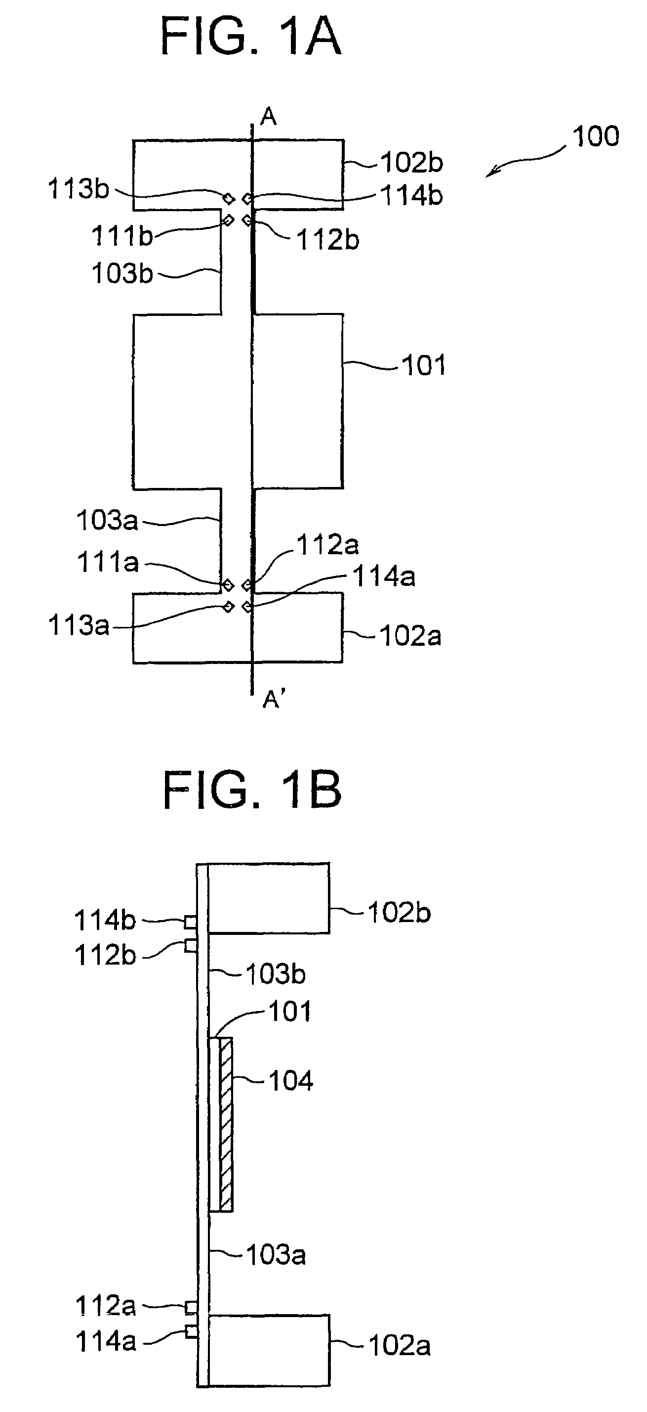
[0037]FIG. 1A denotes a schematic front view of an optical deflector 100 according to a first embodiment of the present invention. FIG. 1B denotes a cross-sectional view along a line A-A′. The structure is such that an elastic supporting portion 103a is extended from a fixed portion 102a. Moreover, an elastic supporting portion 103b is extended from the other fixed portion 102b. A movable plate 101 is formed on an opposite side of a side of the elastic supporting portions 103a and 103b to which the fixed portions 102a and 102b are connected. A mirror surface 104 is formed on a rear surface of the movable plate 101. The mirror surface 104 is made of a material such as aluminum.
[0038]Two active resistors 111a and 112a are formed near a portion (near a connecting portion) on the elastic supporting portion 103a where the fixed portion 102a is connected. Moreover, two reference resistors 113a and 114a are formed near a portion (near a connecting portion) on the fixed portion 102a where t...
second embodiment
[0057]FIG. 5A denotes a schematic front view of an optical deflector 200 according to a second embodiment of the present invention. FIG. 5B denotes a cross-sectional view of FIG. 5A taken along a line E-E′. Same reference numerals are used for portions identical with the portions in the first embodiment.
[0058]The two elastic supporting portions 103a and 103b are extended from the fixed portions 102a and 102b respectively. The movable plate 101 is formed on the opposite side of the side of the elastic supporting portions 103a and 103b to which the fixed portions 102a and 102b are connected. The mirror surface 104 is formed on the rear surface of the movable plate 101. The mirror surface 104 is made of a material such as aluminum.
[0059]The two active resistors 111a and 112a are formed near the portion (near the connecting portion) of the elastic supporting portion 103a where the fixed portion 102a is connected. Moreover, the two reference resistors 113a and 114a are formed near the po...
third embodiment
[0067]FIG. 6A denotes a schematic front view of an optical deflector 300 according to a third embodiment of the present invention. FIG. 6B denotes a cross-sectional view taken along a line F-F′ in FIG. 6A. Same reference numerals are used for portions identical with the portions in the first embodiment.
[0068]The two elastic supporting portions 103a and 103b are extended from the fixed portions 102a and 102b respectively. The movable plate 101 is formed on the opposite side of the side of the elastic supporting portions 103a and 103b to which the fixed portions 102a and 102b are connected. The mirror surface 104 is formed on the rear surface of the movable plate 101. The mirror surface 104 is made of a material such as aluminum.
[0069]An active resistor 611a is formed near a portion (near the connecting portion) on the elastic supporting portion 103 where the fixed portion 102a is connected. Moreover, three reference resistors 612a, 613a, and 614a are formed near the portion (near the...
PUM
 Abstract
Description
Claims
Application Information
 - R&D
- Intellectual Property
- Life Sciences
- Materials
- Tech Scout
- Unparalleled Data Quality
- Higher Quality Content
- 60% Fewer Hallucinations
Browse by: Latest US Patents, China's latest patents, Technical Efficacy Thesaurus, Application Domain, Technology Topic, Popular Technical Reports.
© 2025 PatSnap. All rights reserved.Legal|Privacy policy|Modern Slavery Act Transparency Statement|Sitemap|About US| Contact US: help@patsnap.com


