
Systems and methods for thermal sensing

a technology of thermal sensing and system, applied in the field of electronic devices, can solve the problems of increasing the amount of heat generated in the circuit, increasing the power that is typically consumed by the integrated circuit, and increasing the complexity of the integrated circuit such as microprocessors, so as to achieve efficient control of the operation of the different parts

Active Publication Date: 2009-05-19
KIOXIA CORP +2
View PDF10 Cites 11 Cited by
  • Summary
  • Abstract
  • Description
  • Claims
  • Application Information

AI Technical Summary

Benefits of technology

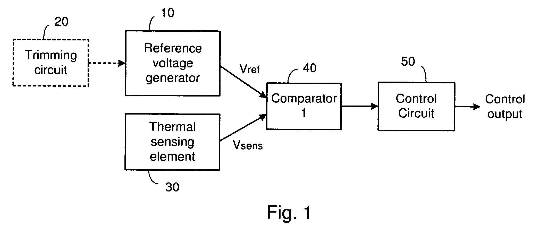
[0011]One or more of the problems outlined above may be solved by the various embodiments of the invention. Broadly speaking, the invention includes systems and methods for positioning thermal sensors within an integrated circuit in a manner that provides useful thermal measurements corresponding to different parts of the integrated circuit. This may enable control circuitry to efficiently control operation of the different parts of the integrated circuit based upon the distinct temperature measurements.

Problems solved by technology

Integrated circuits such as microprocessors are becoming increasingly complex.
As the number of circuit components and functions grows, the amount of power that is typically consumed by these integrated circuits typically also increases.
With the increased power consumption of the circuits, the amount of heat generated within the circuits increases as well.
This heat may affect the performance of the devices, and may even cause the devices to fail.
As a result of the dangers presented by the generation of increased amounts of heat in electronic devices, it is often necessary to be able to detect temperatures within these devices.
There are several problems with this conventional approach for measuring the temperature of an integrated circuit.
One of the problems relates to the positioning of the thermally sensitive on-chip component of the sensor in order to obtain the best temperature measurement.
Conversely, if the temperature measurements are averaged, the chip may not be shut down, even though one of the sensors indicates that a safe temperature threshold has been exceeded.

Method used


Image

  • Systems and methods for thermal sensing
  • Systems and methods for thermal sensing
  • Systems and methods for thermal sensing

Examples


Embodiment Construction

[0025]One or more embodiments of the invention are described below. It should be noted that these and any other embodiments described below are exemplary and are intended to be illustrative of the invention rather than limiting.

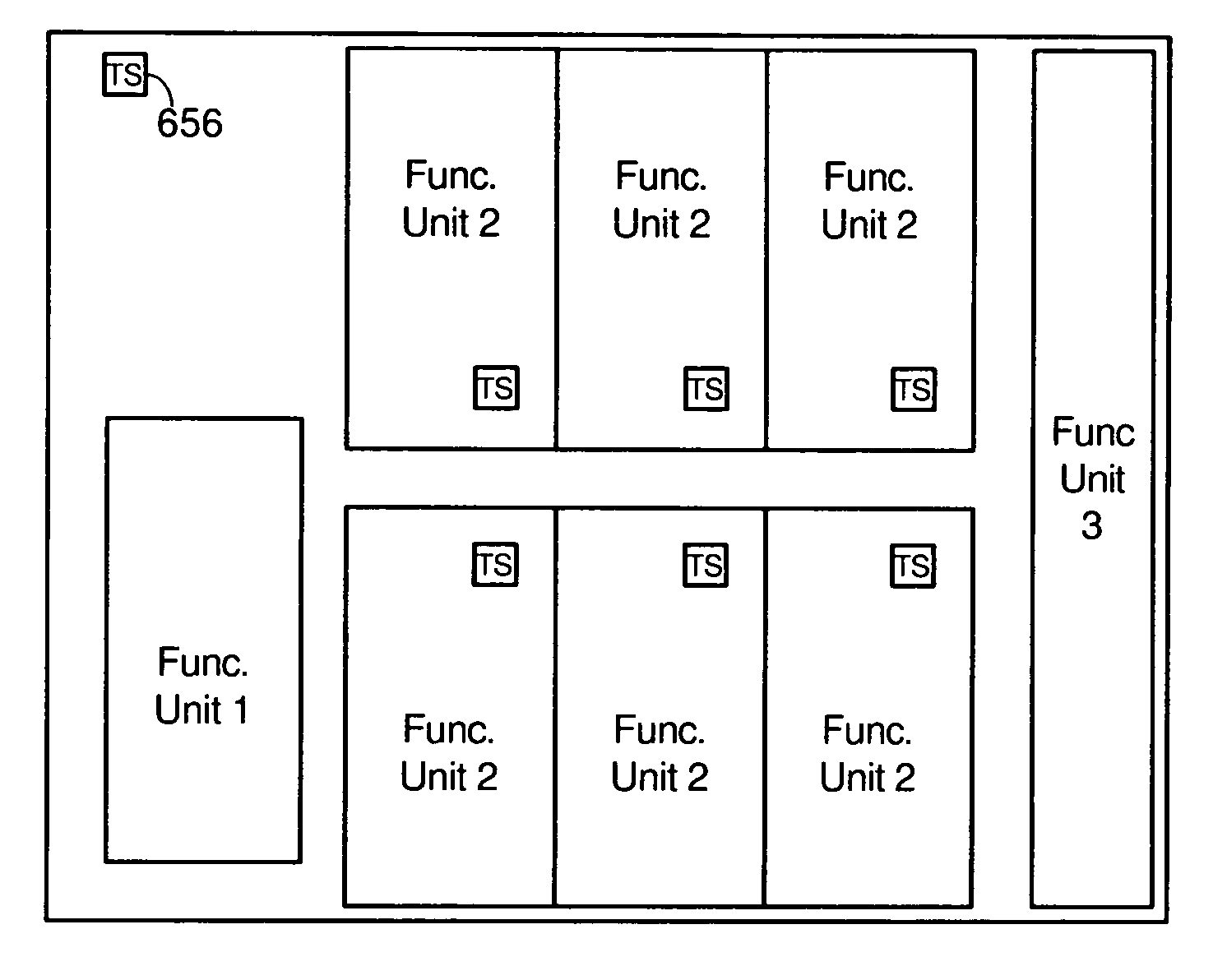
[0026]Broadly speaking, the invention includes systems and methods for positioning thermal sensors within an integrated circuit in a manner that provides useful thermal measurements corresponding to different functional blocks of the integrated circuit. This may enable control circuitry to efficiently control operation of the different parts of the integrated circuit based upon the distinct temperature measurements.

[0027]In one embodiment, a thermal sensing system is implemented in an integrated circuit having multiple, duplicate functional blocks. These duplicate functional blocks may, for instance, be processor cores in a multiprocessor integrated circuit chip. While each of the duplicate functional blocks performs essentially the same function, the differe...


PUM


Abstract

Systems and methods for positioning thermal sensors within an integrated circuit in a manner that provides useful thermal measurements corresponding to different parts of the integrated circuit. In one embodiment, an integrated circuit includes multiple, duplicate functional blocks. A separate thermal sensor is coupled to each of the duplicate functional blocks, preferably in the same relative location on each of the duplicate functional blocks, and preferably at a hotspot. One embodiment also includes thermal sensors on one or more functional blocks of other types in the integrated circuit. One embodiment includes a thermal sensor positioned at a cool spot, such as at the edge of the integrated circuit chip. Each of the thermal sensors may have ports to enable power and ground connections or data connections between the sensors and external components or devices.

Description

RELATED APPLICATIONS[0001]This application claims the benefit of U.S. patent application Ser. No. 11 / 034,644, entitled “Advanced Thermal Sensor,” filed on Jan. 13, 2005 by Munehiro Yoshida.BACKGROUND[0002]1. Field of the Invention[0003]The present invention relates generally to electronic devices, and more particularly to systems and methods for sensing the temperature of devices such as integrated circuits which have multiple, duplicate functional blocks.[0004]2. Related Art[0005]Integrated circuits such as microprocessors are becoming increasingly complex. The circuit components (e.g., transistors, diodes, resistors and the like) that form these devices are, at the same time, becoming increasingly small so that more and more functions may be performed by a particular integrated circuit. As the number of circuit components and functions grows, the amount of power that is typically consumed by these integrated circuits typically also increases. With the increased power consumption o...

Claims


Application Information

Patent Timeline
Patent Type & Authority Patents(United States)
IPC IPC(8): H01L23/58G01K1/14
CPCG06F1/206H01L23/34H01L25/162H01L2924/0002H01L2924/00
Inventor YOSHIDA, MUNEHIROSTASIAK, DANIELWANG, MICHAEL F.JOHNS, CHARLES R.KIHARA, HIROKITAMURA, TETSUJIYAZAWA, KAZUAKITAKIGUCHI, IWAO
Owner KIOXIA CORP
Learn More