
Current-limiting device having a superconductive switching element

a current-limiting device and switching element technology, applied in the direction of super-conductive switchable devices, electrical equipment, emergency protective arrangement details, etc., can solve the problems of super-conductor heat generation, achieve positive magnetic susceptibility, improve local quenching safety, and resist the effect of increasing resistan

Inactive Publication Date: 2009-05-12
SIEMENS AG
View PDF3 Cites 0 Cited by
  • Summary
  • Abstract
  • Description
  • Claims
  • Application Information

AI Technical Summary

Benefits of technology

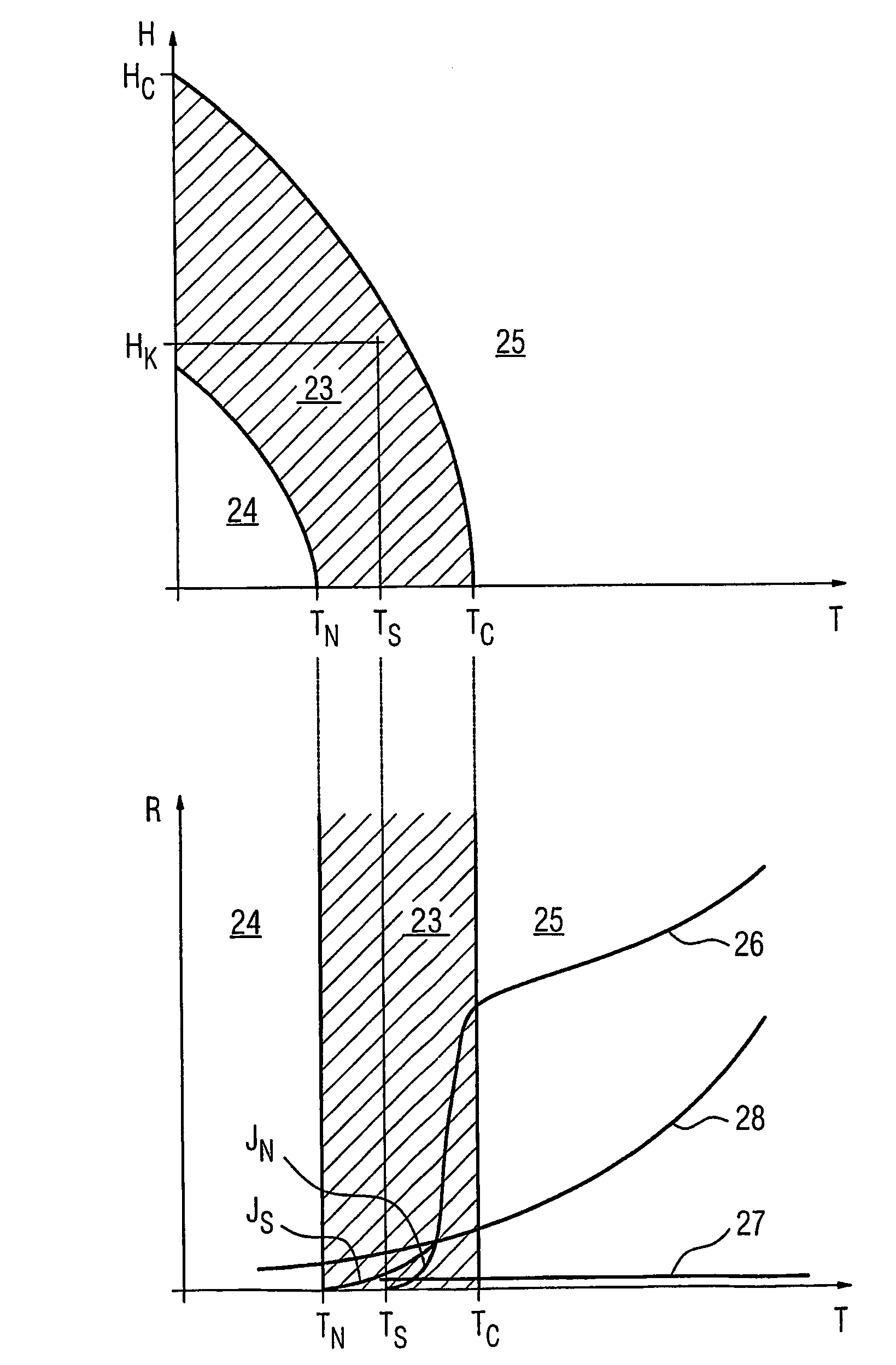
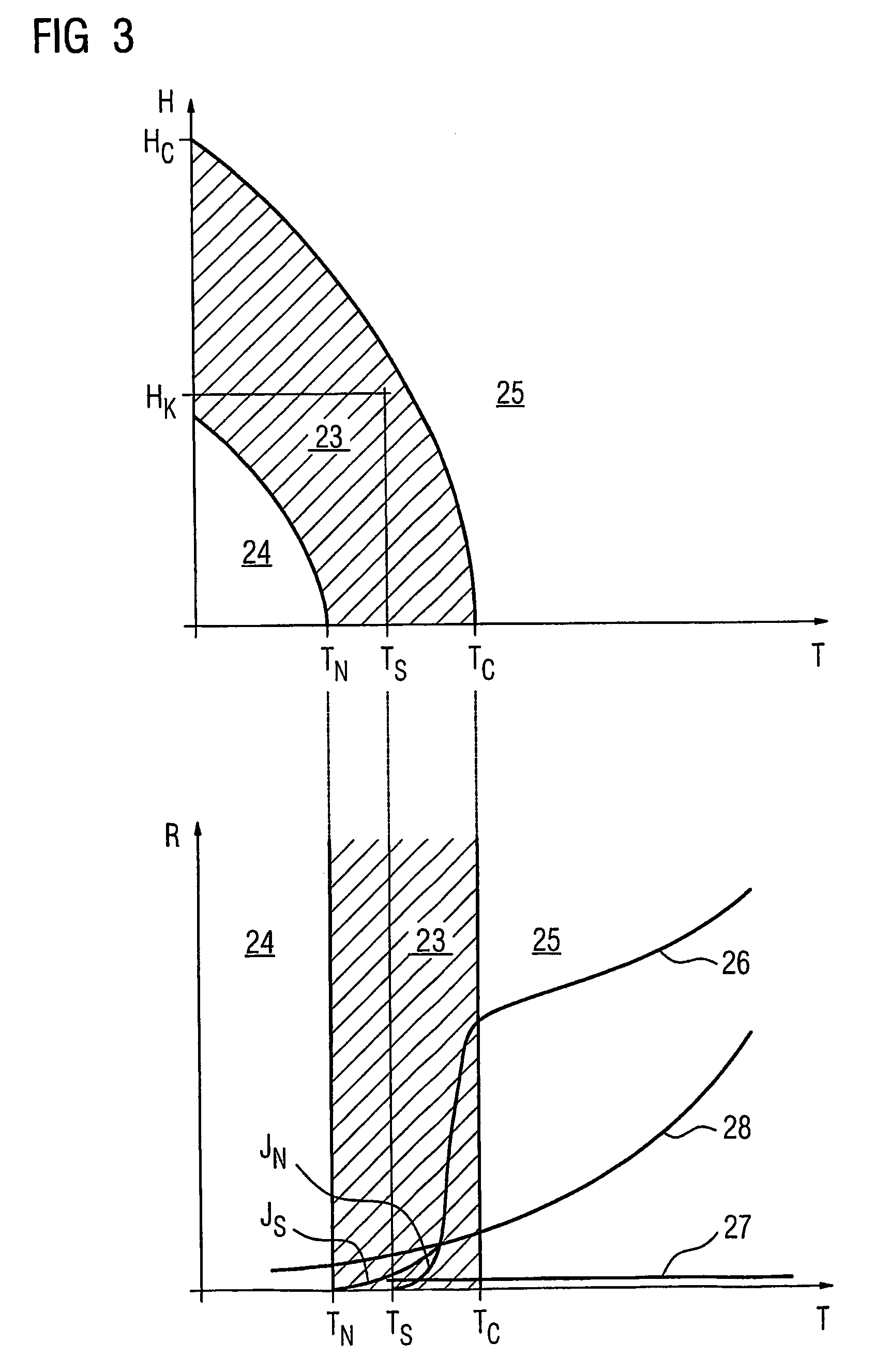
[0008]According to the invention, this object is achieved in that the switching element is designed in such a manner that it is in the Shubnikov phase on reaching the required short-circuit residual current of the current-limiting device when the current is being limited. According to the invention, the superconducting switching element must therefore be designed such that the only minor increase in the electrical resistance in comparison to the quenching of the superconductor during operation in the flux-flow range (that is to say when the superconductor is in the Shubnikov phase) is sufficient to limit the short-circuit current to the short-circuit residual current. This is achieved by the superconducting switching element having a sufficient conductor length to achieve the resistance which is necessary for the required short-circuit residual current just by being in the Shubnikov phase at a temperature which has a sufficient safety margin from the critical temperature (transition to the normally conductive state). The superconducting switching element may in particular be in the form of a strip conductor, which allows the required conductor length to be produced at low cost, in this way.
[0016]It is advantageous for the bypass element to be located outside the cryostat. This results in some of the heat that is produced by the current-limiting process being created in the bypass element and thus outside the cryostat, so that its cooling capacity is always sufficient for the superconducting switching element. In contrast to the situation in known current-limiting devices, the bypass element is, however, operated in parallel with the switching element throughout the entire time during which the current is being limited, that is to say the switching element remains connected to the network.

Problems solved by technology

If a network fault (for example a short) occurs in the network, then the unacceptably high short-circuit current results in the superconducting switching element having a response which is referred to as quenching.
The increase in the resistance of the superconducting switching element associated with this leads to heating of the superconductor.
However, the described principle of operation means that cooling is required before the current limiter is used again.

Method used


Image

  • Current-limiting device having a superconductive switching element
  • Current-limiting device having a superconductive switching element
  • Current-limiting device having a superconductive switching element

Examples


Embodiment Construction

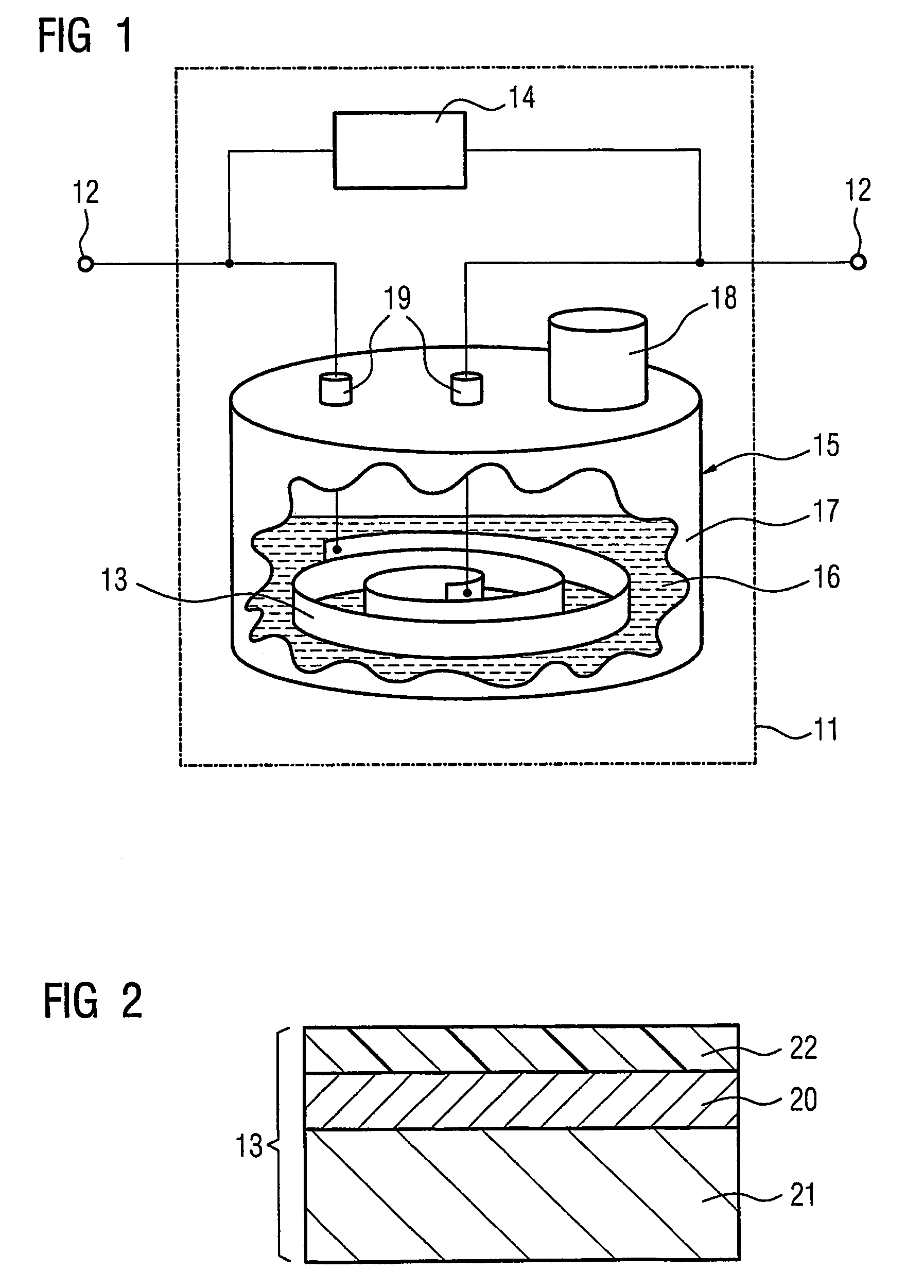
[0021]A current limiting device 11 has two connecting elements 12, by means of which it can be included in an electrical network. The current-limiting device 11 essentially comprises a superconducting switching element 13 and a bypass element 14, which is arranged in parallel with the switching element 13. The switching element 13 is accommodated in a cryostat 15 which, for this purpose, has an insulating container 17 that is filled with liquid nitrogen as the coolant 16. A cold head 18 dissipates the heat from the insulating container. Furthermore, line feeders 19 are provided on the insulating container 17 and allow electrical contact 11 to be made between the switching element 13 and the connecting elements 12 which are located outside the insulating container 17.

[0022]The superconducting switching element 13 is illustrated in the form of a section in FIG. 2. It is composed of a layer composite, with a superconducting layer 20 (for example YBCO) being produced by coating on a com...


PUM


Abstract

An electrical current limiting device has a superconductive switching element. Unlike prior art superconductive current limiters whose switching mechanism is based on a quenching of the switching element, the inventive superconductive switching element is designed in such a manner that it is in the Shubnikov phase when the required short-circuit cutoff current is reached in the event current is limited. This enables the switching element to be operated in an operating state in which the generation of heat is limited to such an extent that the coolant surrounding the superconductor is able to completely dissipate the heat whereby achieving a stationary state at TS. A quenching of the superconductor, which is associated with an exceeding of TC, can thus be actively prevented so that, after an event in which current is limited, the superconductor is not required to be removed from the mains and recooled.

Description

BACKGROUND OF THE INVENTION[0001]1 Field of the Invention[0002]The invention relates to an electronic current-limiting device having a superconducting switching element which is arranged in a cryostat.[0003]2 Description of the Related Art[0004]A current-limiting device of the type mentioned in the introduction is known, for example, from DE 102 30 084 A1. This current-limiting device is operated in an electrical network. The current is carried by the superconducting switching element, which has a negligible small electrical resistance at the operating temperature which is maintained by continuous cooling. If a network fault (for example a short) occurs in the network, then the unacceptably high short-circuit current results in the superconducting switching element having a response which is referred to as quenching. The high current flow produces induction in the super conductor, which first of all slightly increases its electrical resistance. This changes the superconductor to the...

Claims


Application Information

Patent Timeline
Patent Type & Authority Patents(United States)
IPC IPC(8): H02H7/00H02H1/00H10N60/30H10N60/81
CPCH01L39/16H10N60/30
Inventor KRUGER, URSAUSVOLKMAR, RALF-REINER
Owner SIEMENS AG
Learn More