
Coaxial connector

Inactive Publication Date: 2009-05-12
SUYING ELECTRCNICS (DONG GUAN) CO LTD
View PDF5 Cites 8 Cited by
  • Summary
  • Abstract
  • Description
  • Claims
  • Application Information

AI Technical Summary

Benefits of technology

[0006]One object of the present invention is to provide a coaxial connector for enhancing stability of the signal transmission and prolonging the life time of products.
[0007]Another object of the present invention is to provide a coaxial connector that can be readily assembled, thereby promoting the installing efficiency and declining the percentage of inferior products.
[0008]The coaxial connector in accordance with the present invention mainly provides with an insulating base, a central terminal, a first terminal, a second terminal, a waterproof ring, and a metal shell. Wherein, the insulating base includes a lower base and an upper base defining a central stand providing a hole to be penetrated by the central terminal. The central stand has its back to be constructed by a lateral wall, from both ends of which two side walls respectively extended and equidistantly spaced with respect to sides of the central stand. Wherein, one of the two side walls has a deep slot, comprised of a first slot and a second slot, laterally disposed through the lateral wall for receiving the first and second terminals. The first and second terminals have respective secure plates that are correspondingly firmly connected with walls of the first and second slots, and the secure plates further contain a plurality of fixing flanks with wave-shaped contacts attaching thereon. The wave-shaped contacts especially have high resilience and a capability of readily bouncing back so as to guarantee a firm contact of the switch button and the coaxial connector while being subjected to a long-term compression and enhance the quality of the mutual communications.
[0009]Further by the integration of the lower base with the upper base, the above terminals are firmly positioned in the insulating base, so as to avoid deviation of the terminals and prevent bad influence on the connector arising from the departure. Moreover, signals can be received and transmitted by the central terminal of the coaxial connector contacting a separate antenna of the mobile communication device; thereby, communication can be transported or disconnected by the contact or interruption between the switch button and the wave-shaped contacts protruded from the first and second terminals. Owing to the characteristic of the wave-shaped contacts, they are able to maintain their resilience along with a firm connection with the switch button for ensuring the stability of the mutual signal transmissions among the mobile communication devices.
[0010]Therefore, the present invention applies the correlation of above elements to firmly position the terminals and the insulating base and accompanies the wave-shaped contacts with high elasticity that densely touch and cooperate with the switch button, thereby achieving a more stable signal transmission of communication, a quick assembling of the coaxial connector, and prolonging products life time

Problems solved by technology

However, the infirm installation of the conventional coaxial connector commonly exists while the terminals are not well incompliance with its insulating base, which negatively incurs the deviation and departure of terminals from the connector or causes other inferiors.
Over a long-term compression, the elasticity of the terminals becomes weak, and the contact of the terminals and the switch button is relatively affected, which may result of an improper contact and clogged communication and obstruct the implement of the public security.
That is, if the improper contact and clogged communication occur, the suspicious staffs may have the opportunity of escaping while on duty and make serious consequences.
Further, the conventional connector requires complex manufactures and installations, and the replacement with a new one usually needs complicated procedures and even causes the unwillingness of using the connector for people.

Method used


Image

  • Coaxial connector
  • Coaxial connector
  • Coaxial connector

Examples


Embodiment Construction

[0019]Before describing in greater detail, it should note that the like elements are denoted by the similar reference numerals throughout the disclosure.

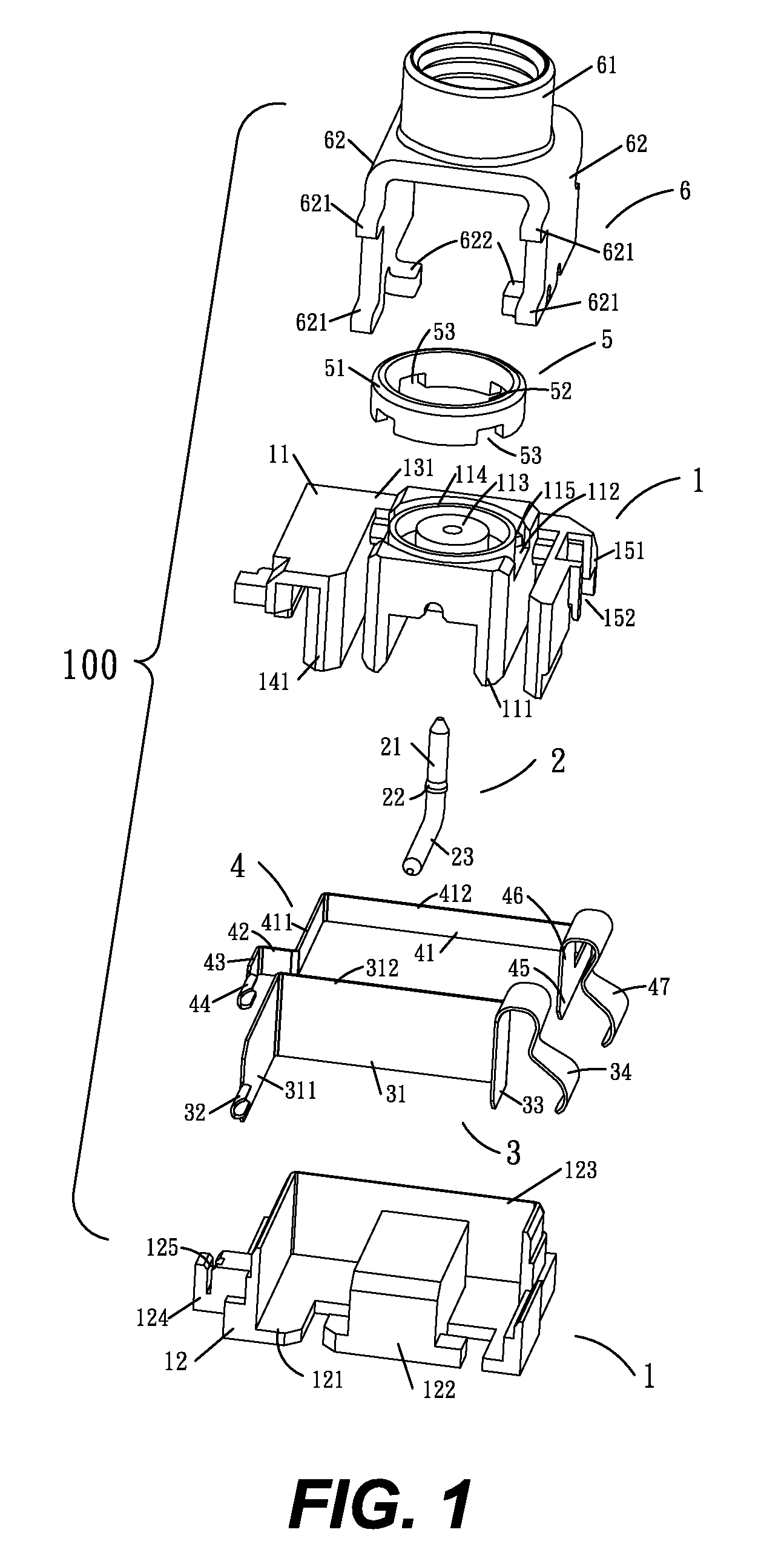
[0020]Referring to FIG. 1, the coaxial connector 100 of the present invention mainly provides with an insulating base 1, a central terminal 2 disposed in the insulating base 1, a first terminal 3, a second terminal 4, a waterproof ring 5, and a metal shell 6.

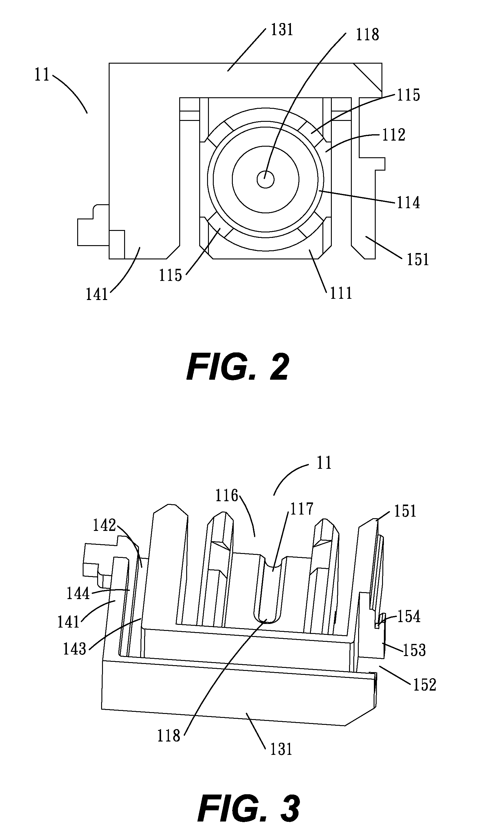
[0021]Referring to FIGS. 1, 2, and 3, the insulating base 1 includes a lower base 12 and an upper base 11. Wherein, the upper base 11 has a central stand 111 defining an unclosed round recess112 on its top surface, where a round protrusion 114, including a central cylinder 113 disposed among it, is protruded. A plurality of gripping blocks 115 are equidistantly mounted around the outer periphery of the round protrusion 114 and the inner wall of the unclosed round recess 112. An indentation 116 with a U-shaped notch 117 provided thereon is defined on the bottom surface of the cen...


PUM


Abstract

The present invention pertains to a coaxial connector including an insulating base disposing a central terminal passing through a hole thereof to facilitate signal transmission, a first and a second terminals including secure plates to be disposed on a deep slot of the insulating base, a waterproof ring, and a metal shell. Wherein, the secure plates have fixing flanks to strengthen the firmness between the terminals and the insulating base. Wave-shaped contacts with high resilience further protrude from the fixing flanks to prop against or separate from the switch button of the mobile communication device for getting through or disconnecting the communication. Through the highly elastic contacts, the terminals still maintain to firmly contacting with the switch button or rapidly bouncing back even when being subjected to a long-term compression and ensure the stability of the mutual signal transmission among the mobile communication devices.

Description

BACKGROUND OF THE INVENTION[0001]1. Field of the Invention[0002]The present invention relates to a coaxial connector, in particular to a coaxial connector applying for mobile communication devices.[0003]2. Description of the Related Art[0004]There is a wide application of apparatus used to a mobile communication device in the real life, for instance of an intercom which is one of the main communication devices for functions of public securing or traffic controlling. Conventionally, the intercom mainly has a body and an antenna system to receive external signals. For receiving signals, the antenna is typically bound to an exteriorly assembled coaxial connector of the body providing with a signal converting circuit. In addition, the coaxial connector has to dispose terminals therein which further engage with a switch button in the body hence achieving a mutual communication. Therefore, the attachment of the terminals with the coaxial connector is a critical factor implementing to effi...

Claims


Application Information

Patent Timeline
IPC IPC(8): H01R12/00
CPCH01R24/46H01R24/52H01R2103/00
Inventor TSAI, CHIH HONGOU, QING HAI
Owner SUYING ELECTRCNICS (DONG GUAN) CO LTD
Learn More