Telescopic support

Active Publication Date: 2016-07-05
DAVIS BRADFORD L
View PDF37 Cites 12 Cited by
  • Summary
  • Abstract
  • Description
  • Claims
  • Application Information

AI Technical Summary

Benefits of technology

The present invention provides a telescopic support with at least three bearing sets, each having at least two roller bearings disposed with a rotational axis directed substantially towards a longitudinal axis of the telescopic support. The telescopic support may further include a guide plate that slides within the telescopic support and aids in stabilizing the telescopic support as it extends and retracts. This design provides enhanced stability to substantially avoid misalignment between inner and outer supports of the telescopic support, and applications in which the telescopic support is used, such as in an overbed table, may be less prone to wobble or tipping.

Problems solved by technology

However, as the telescopic support extends, the conventional bearing configuration often times loses its ability to maintain axial alignment under bending, torsional, or axial loads, or a combination thereof.
If axial alignment is not maintained, the telescopic support may seem to tip or wobble, either of which can be unpleasant in the context of a tabletop.
These variations can affect the ability to consistently manufacture a telescopic support that maintains axial alignment under various loads, and can result in significant wobble.
This process of measuring, machining and fitting a non-standard spacer for each support can be laborious and expensive.
In other words, machining and fitting a non-standard spacer specific to the dimensions of each support can add significant cost to the support.
Additionally, attempts to repair such a support can be impeded because non-standard parts can be laborious and costly to replace.

Method used


Image

  • Telescopic support
  • Telescopic support
  • Telescopic support

Examples


Embodiment Construction

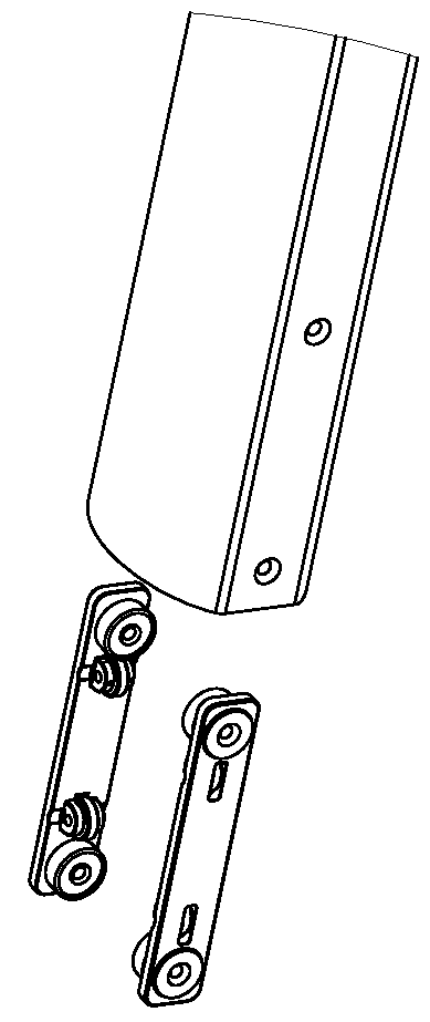
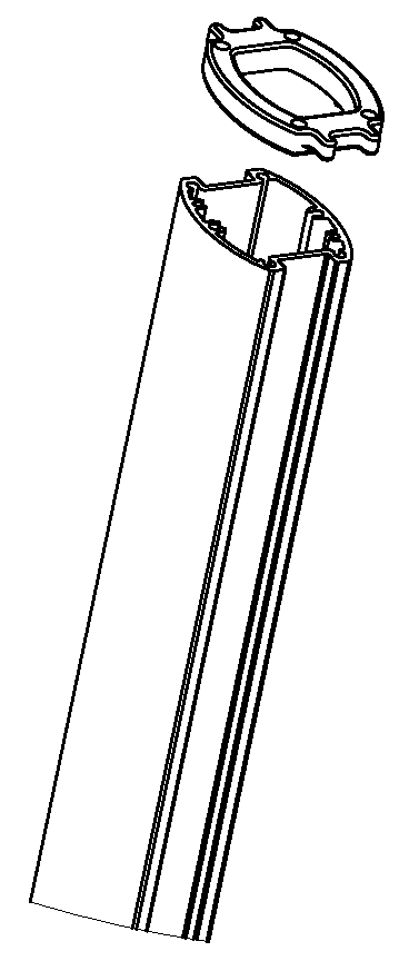
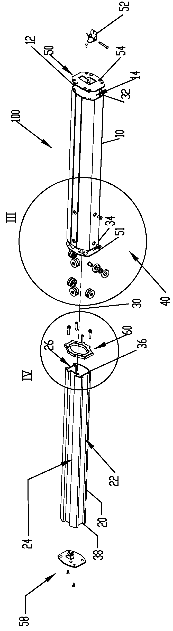
[0025]A telescopic support in accordance with one or more embodiments of the present invention is shown in FIG. 2, and generally designated 100. As set forth below, the telescopic support 100 may include an outer support tube 10 and an inner support 20, the outer support tube 10 and the inner support 20 being capable of moving with respect to each other such that the telescopic support 100 can extend and retract. The inner support 20 may be received within an interior space 14 of the outer support tube 10 defined by an interior wall 12 of the outer support tube 10. In particular, the inner support 20 may be movable in a direction substantially parallel to a longitudinal axis 30 shared and defined by the inner support 20 and the outer support tube 10. A substantial portion of the inner support 20 may be movably received within the interior space 14 such that the telescopic support 100 may be substantially retracted. Conversely, the inner support 20 may be movably extended out from th...


PUM


Abstract

A telescopic support having an outer support tube and an inner support that move with respect to each other along a longitudinal axis of the telescopic support. At least three bearing sets having roller bearings are affixed to one of the outer support tube or the inner support. The roller bearings of a bearing set may be spaced apart along the longitudinal axis, and may be configured such that a rotational axis of each of the roller bearings is substantially directed toward the longitudinal axis of the telescopic support.

Description

TECHNICAL FIELD[0001]The present invention relates to telescopic supports, and more particularly to telescopic supports having roller bearings.BACKGROUND[0002]Telescopic supports are used in a wide range of applications, including applications related to table and desk supports. In these applications, the telescopic support is often times disposed between a base and a tabletop to enable vertical adjustment of the tabletop. This conventional adjustable height table can be found in a variety of configurations and settings, such as in overbed tables for use in hospitals.[0003]Conventional telescopic supports, in some cases, utilize an inner tube, an outer tube, and bearings therebetween. In this conventional configuration, the bearings are disposed to try to maintain axial alignment of the inner and outer tubes while allowing vertical movement of the tubes with respect to each other. The bearings also are disposed in a fixed relationship to one of the inner or outer tubes, and ride on ...

Claims


Application Information

Patent Timeline
IPC IPC(8): A47B9/20F16M11/26A47B23/04
CPCA47B9/20F16M11/26A47B23/046F16C3/035F16C29/008F16M11/38F16M11/425
Inventor DAVIS, BRADFORD L.
Owner DAVIS BRADFORD L
Why Eureka
Try Eureka