
Clamp for a rail transducer

a transducer and clamping technology, applied in the field of clamps, can solve the problems of temporary and eventually permanent distortion of the rail profil

Inactive Publication Date: 2009-05-12
ARMSCOR BUSINESS
View PDF9 Cites 16 Cited by
  • Summary
  • Abstract
  • Description
  • Claims
  • Application Information

AI Technical Summary

Benefits of technology

The clamp provides consistent and secure contact between the transducer and rail, accommodating rail distortions and maintaining signal quality over long distances by ensuring adequate contact and alignment for optimal wave excitation and propagation.

Problems solved by technology

This is made difficult by the fact that the passage of rolling stock over the rail causes temporary and eventually permanent distortion of the rail profile.

Method used


Image

  • Clamp for a rail transducer
  • Clamp for a rail transducer

Examples


Embodiment Construction

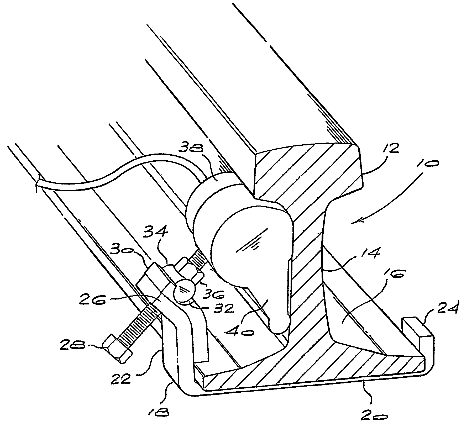
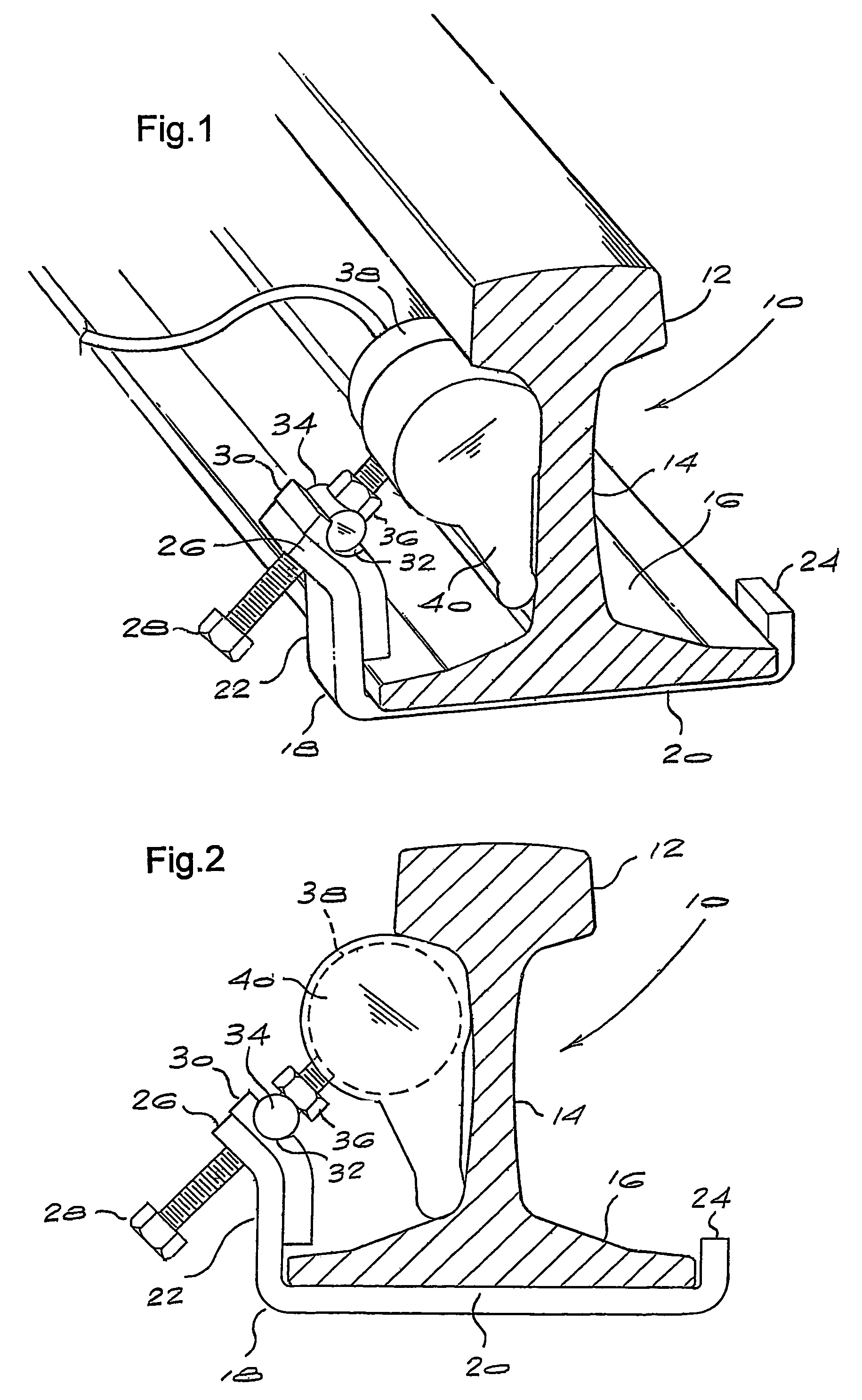
[0019]Referring to the drawings, a steel train rail 10 forming part of a railway line is shown. The rail 10 comprises a head 12, an upright web 14 and a flattened foot 16.

[0020]Fitted under the foot of the rail is a bracket 18 forming part of a clamp of the invention, the bracket having a foot portion 20 which fits under the foot of the rail, and an upright arm 22 at one end of the foot portion. The bracket 18 is formed from a single piece of steel bar, the thickness of the bar and the type of steel being selected to provide the desired characteristics, particularly suitable resilience or springiness. For example, type 316 stainless steel is a suitable material, having excellent corrosion resistance, a high tensile strength to enable a high clamping force to be achieved, and a suitable degree of resilience or springiness to enable the necessary clamping force to be maintained, as described below. Another material having suitable resilience and mechanical properties could be used ins...


PUM

PropertyMeasurementUnit
standoff distanceaaaaaaaaaa
distancesaaaaaaaaaa
forceaaaaaaaaaa

Abstract

A clamp for securing a transducer to a train rail comprises a bracket having a base which engages the foot of the rail. An upright arm at one end of the base extends adjacent the web of the rail and carries a threaded adjuster which engages the transducer and urges it into contact with the rail. The clamp is sufficiently resilient so that, when the adjuster is tightened to a predetermined extent, both temporary and permanent de formation of the rail can be accommodated without difficulty.

Description

[0001]This application is a U.S. National Phase of International Patent Application Ser. No. PCT / IB2004 / 001406, filed May 6, 2004 which claims priority to South African Patent Application No. 2003 / 3505 filed May 7, 2003.BACKGROUND OF THE INVENTION[0002]THIS invention relates to a clamp for securing a transducer to a train rail.[0003]In order to monitor the condition of train rails, acoustic or ultrasonic transducers are used to excite a rail so that the resulting propagation modes travel for a substantial distance along the rail. A receiver unit located a substantial distance away from the transducer can detect such propagation modes and can be used to provide an indication of the condition of the rail, and can thus be used to warn of a break in the rail or other mechanical damage. A system of this kind is described in South African patent no. 99 / 6936.[0004]In systems of the kind described above, it is important that the transducer used to excite the rail should be held in firm and ...

Claims


Application Information

Patent Timeline
Patent Type & Authority Patents(United States)
IPC IPC(8): B61K9/00B61K9/10G01N29/22
CPCB61K9/10G01N29/223G01N2291/2623E01B26/00
Inventor SHERRIFF, BRIANBURGER, FRANCOIS ALVYN
Owner ARMSCOR BUSINESS
Learn More