
Derived clock synchronization for reduced skew and jitter

Active Publication Date: 2009-04-28
NVIDIA CORP
View PDF8 Cites 20 Cited by
  • Summary
  • Abstract
  • Description
  • Claims
  • Application Information

AI Technical Summary

Benefits of technology

[0004]Clock skew and / or jitter can be especially problematic in synchronous circuits. For example, where a first circuit is intended to communicate synchronously with a second circuit (e.g., the first circuit and the second circuit may be contained in a graphics processor chip), clock skew and / or jitter reduce the amount of time in which the circuits can communicate or provide other useful work. Assume for example that clock skew and / or jitter result in 100 picoseconds (ps) of variation between clocks driving the first circuit and the second circuit. If the first circuit and the second circuit are clocked at 200 MHz, then each clock cycle comprises 5 nanoseconds (ns) and clock skew and / or jitter comprises a relatively insignificant portion (2%) of the clock period. However, if the first circuit and the second circuit are clocked at 2 GHz, then each clock cycle comprises only 500 ps and clock skew and / or jitter comprises a significant portion (20%) of the clock period. Accordingly, the useful time in which the first circuit and the second circuit can communicate is reduced to only 400 ps per clock period. Reducing skew and / or jitter thus becomes increasingly important as clock frequencies increase.

Problems solved by technology

Clock skew and / or jitter can be especially problematic in synchronous circuits.
In addition, if a clock signal is distributed to two or more endpoints that are intended to operate synchronously, the distribution network for the clock signal can comprise significant length.

Method used


Image

  • Derived clock synchronization for reduced skew and jitter
  • Derived clock synchronization for reduced skew and jitter
  • Derived clock synchronization for reduced skew and jitter

Examples


Embodiment Construction

System Overview

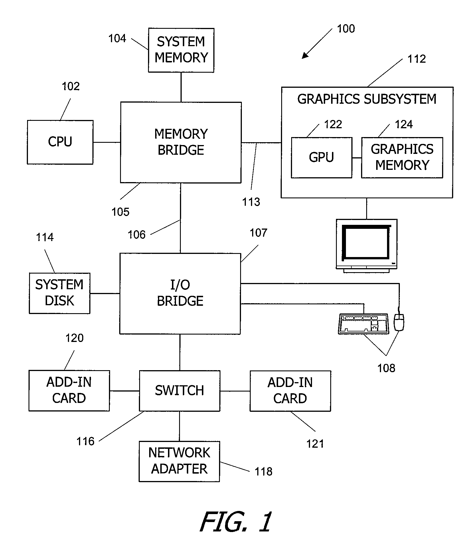
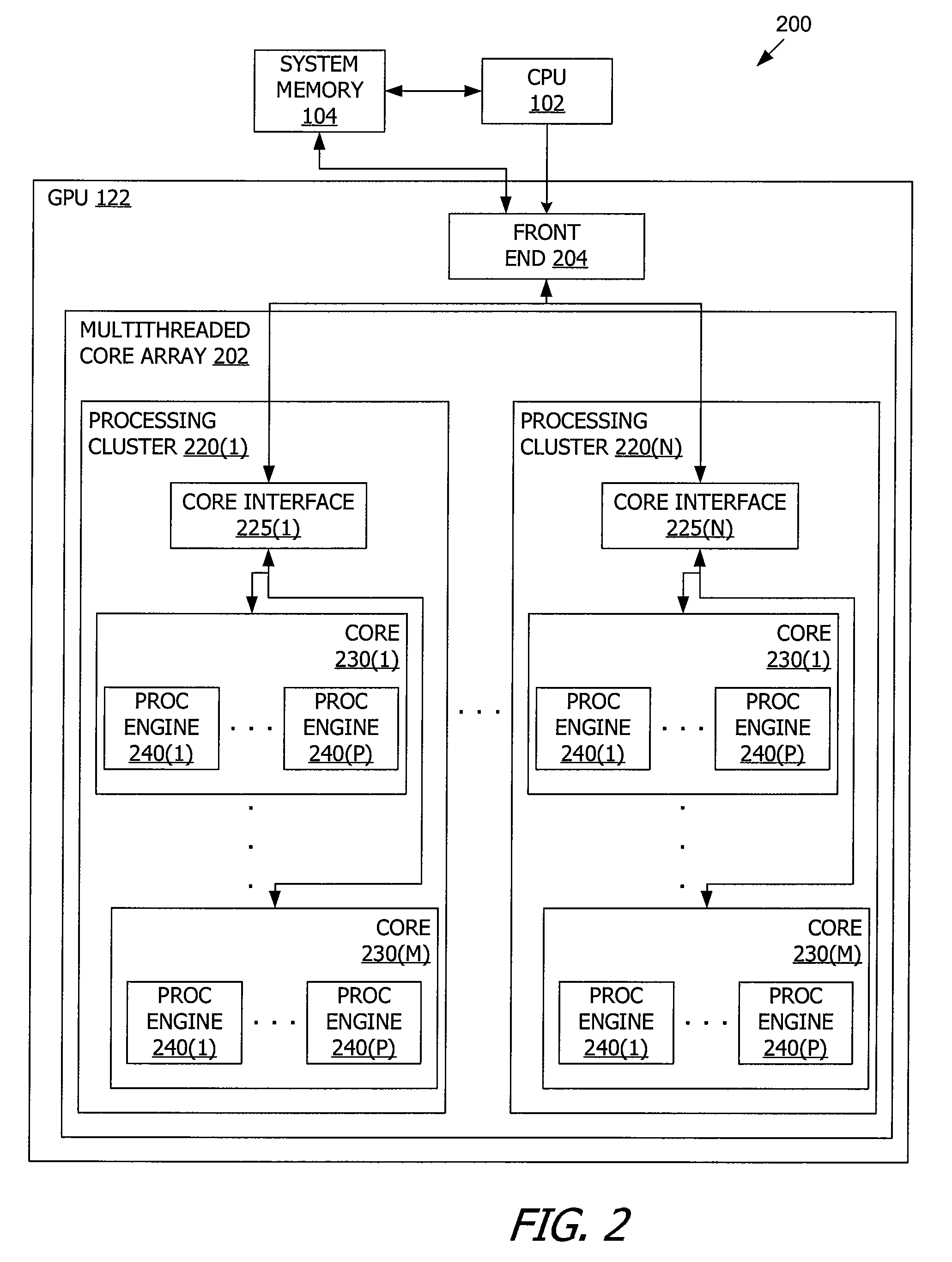
[0015]FIG. 1 is a block diagram of a computer system 100 according to an embodiment of the present invention. Computer system 100 is merely exemplary, and a number of alterations may be made to computer system 100. Computer system 100 includes a central processing unit (CPU) or control processor 102 and a system memory 104 communicating via a communications path that includes a memory bridge 105. Memory bridge 105 (e.g. a Northbridge chip) is connected via a communication path 106 (e.g., a point-to-point connection using the HyperTransport protocol) to an I / O (input / output) bridge 107. I / O bridge 107 (e.g. a Southbridge chip) receives user input from one or more user input devices 108 (e.g., keyboard, mouse) and forwards the input to CPU 102 via communication path 106 and memory bridge 105. Visual output is provided on a pixel based display device 110 (e.g., a CRT or LCD based monitor) operating under control of a graphics subsystem 112 coupled to memory bridge 105 vi...


PUM


Abstract

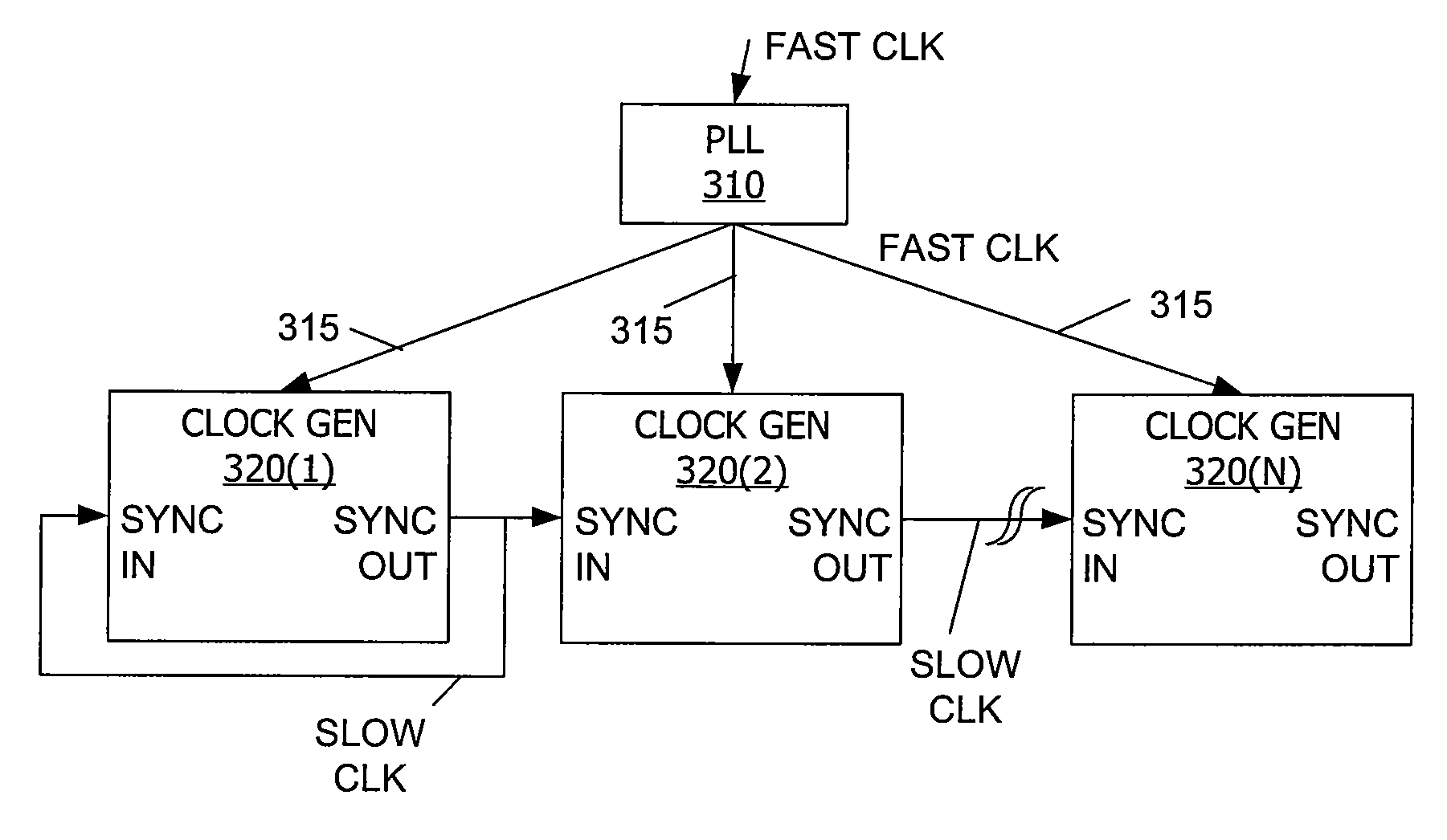
Two or more circuits (e.g. processing cores of a graphics processor) operate synchronously at a fast clock frequency. A core interface to each of the processing cores is designed to communicate in synchronous fashion with one or more other core interfaces at a slow clock frequency. The fast clock is distributed to each processing core in a manner that provides minimized skew and jitter, e.g. with a balanced tree network. The slow clock is locally derived from the fast clock in each core interface. One of the core interfaces is selected to provide a synchronism signal, and the synchronism signal is distributed among the multiple core interfaces to synchronize the locally derived slow clocks.

Description

BACKGROUND OF THE INVENTION[0001]As expectations for ever-more capable electronic devices continues to grow, devices such as personal computers are expected to provide increasingly fast processing to deliver applications such as streaming video, rapid Internet surfing, and realistic computer gaming. One strategy to provide fast processing is to design circuitry to operate at higher clock frequencies, since other things being equal, operating circuitry at higher clock frequencies allows the circuitry to perform a given function in a shorter amount of time. For example, whereas in 1995 a Pentium chip from Intel Corp. could be operated with a 100 MHz (100 million cycles / second) clock rate, by 2002 an Intel Pentium 4 could be operated with a clock rate of 3 GHz (three billion cycles / second).[0002]Such high clock rates can lead to a number of design issues. For example, one issue that can cause problems is jitter. Jitter is an abrupt and unwanted variation in a signal, such as a variance...

Claims


Application Information

Patent Timeline
IPC IPC(8): G06F1/00G06F11/00H03L7/06
CPCG06F1/12H03L7/06
Inventor SONI, TEJVANSH S.
Owner NVIDIA CORP
Learn More