Input arrangement for a low-noise amplifier pair

a low-noise amplifier and input arrangement technology, applied in the field of input arrangement for low-noise amplifier pairs, can solve the problems of increasing the noise figure by the same amount, more attenuation in the signal, and reducing the attenuation caused by the transmission path, so as to reduce the loss of the front stage of the receiver before the low-noise amplifiers are reduced, the effect of reducing the loss

Active Publication Date: 2009-04-28
INTEL CORP
View PDF6 Cites 3 Cited by
  • Summary
  • Abstract
  • Description
  • Claims
  • Application Information

AI Technical Summary

Benefits of technology

[0012]The invention has an advantage that the losses of the front stage of a receiver before the low-noise amplifiers are reduced, i.e. the attenuation caused by the transmission path is reduced. This is due to that the transmission path from the antenna to the low-noise amplifiers is formed of a smaller number of lossy parts and also to that placing these parts on an ordinary circuit board is avoided. The reduction of the losses means that the noise figure of the front stage improves, in which case inferior noise values can be allowed for its both LNAs, which further means saving of costs in amplifiers. In addition, the invention has the advantage that no discrete coil is needed for the matching of the input impedance of the LNA, and the matching thus becomes more accurate. Furthermore, the invention has the advantage that it simplifies the structure of the front stage, which means saving of costs in production.

Problems solved by technology

Losses on the transmission path cause attenuation in the signal, directly increasing the noise figure by the same amount.
On the other hand, the divider, the phase shifter and the additional wiring required by them cause more attenuation in the signal, which, as mentioned, directly impairs the noise figure of the LNA.
The losses of the matching circuits on the input side of the amplifiers are also significant.
In addition, the coil of the matching circuit causes a production problem, because the variation of its inductance is so wide in practice that the impedance matching on the operating band may be insufficient.
This means additional losses in the divider.
The cabling does not cause losses in this case, but a new drawback is caused by the dielectric losses that arise at the low-pass filter in the circuit board.
However, in that case there is a flaw of a significant increase in production costs.

Method used


Image

  • Input arrangement for a low-noise amplifier pair
  • Input arrangement for a low-noise amplifier pair
  • Input arrangement for a low-noise amplifier pair

Examples


Embodiment Construction

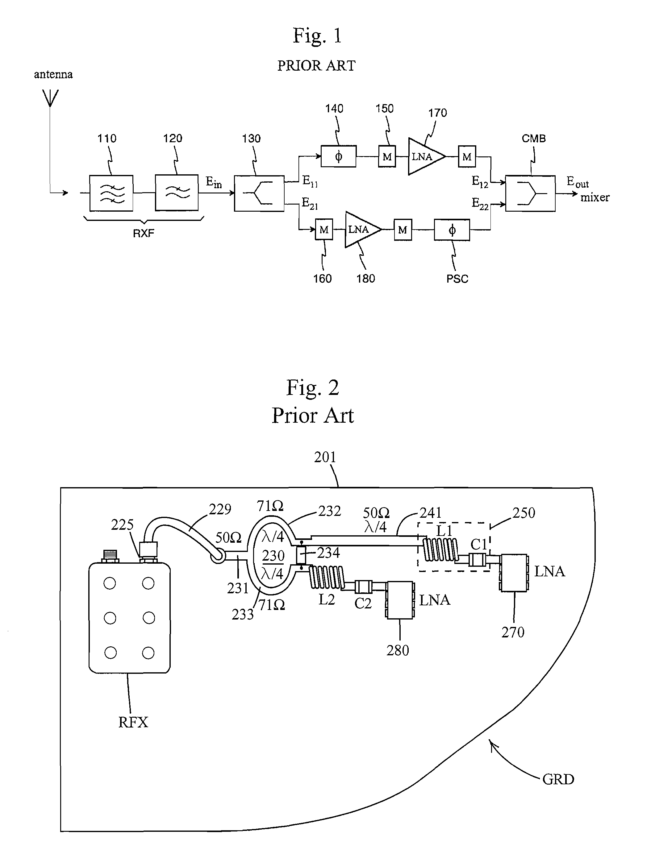
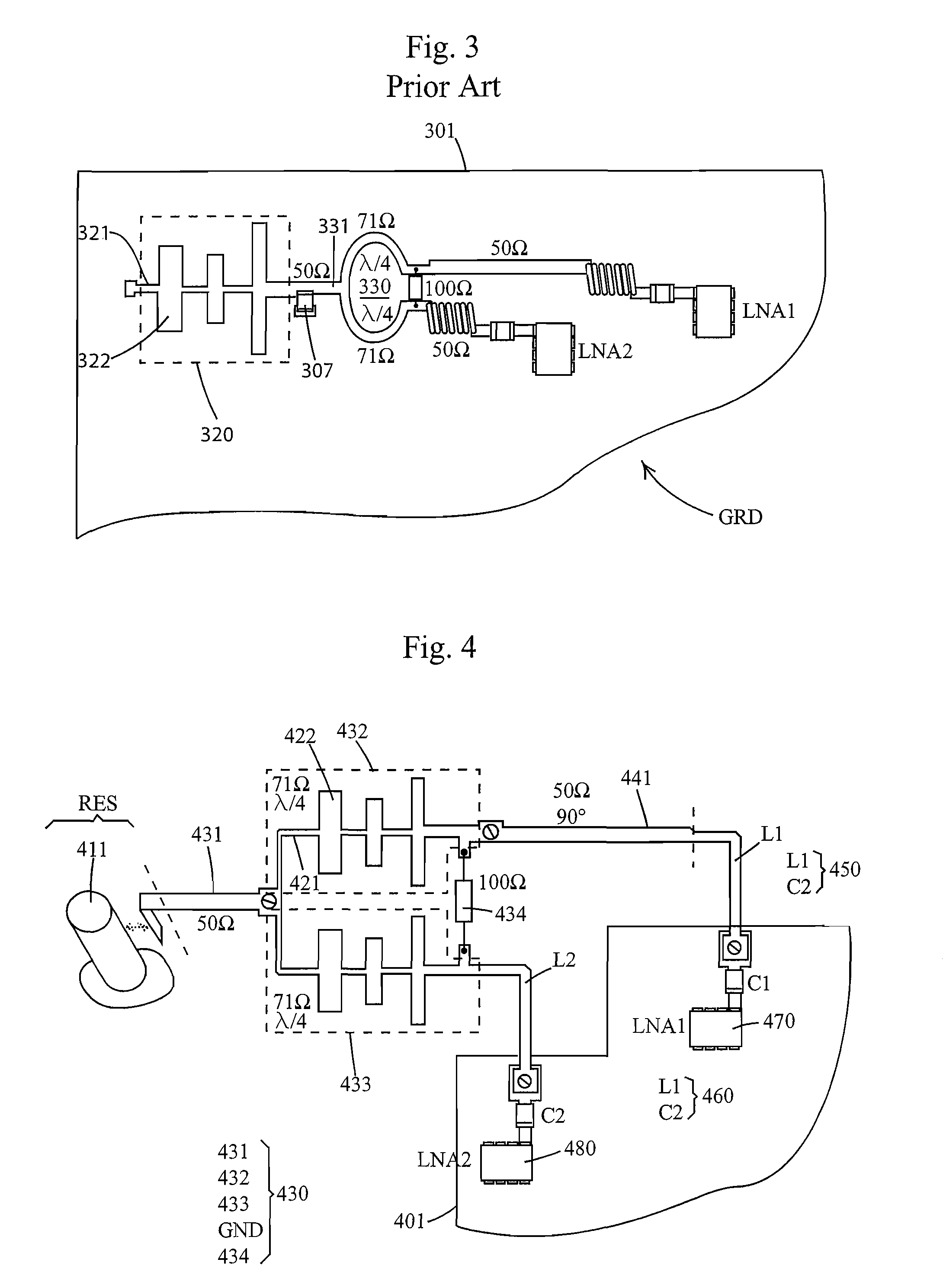
[0022]FIGS. 1, 2 and 3 were already explained in connection with the description of the prior art.

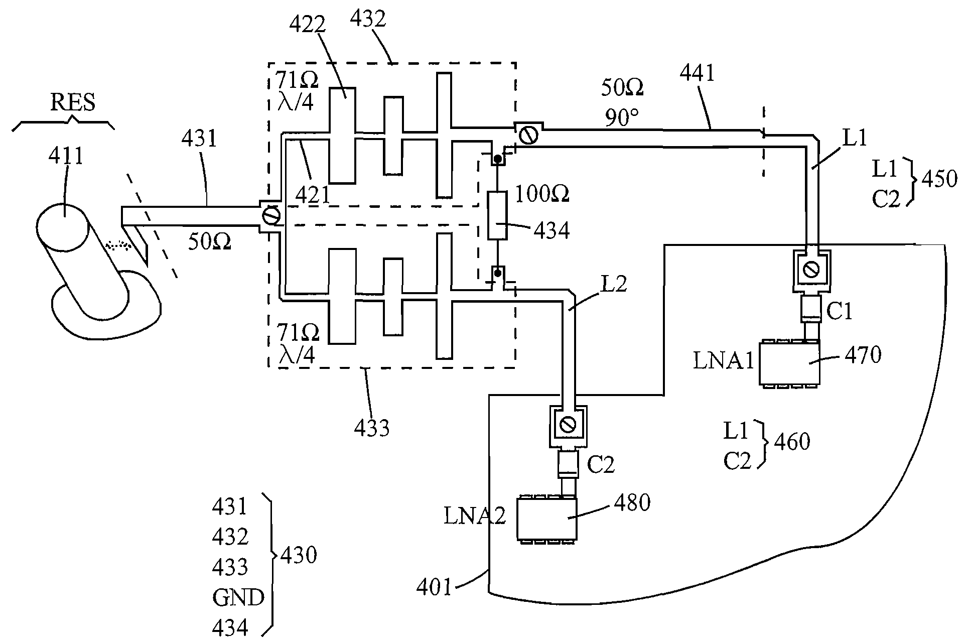
[0023]FIG. 4 is an example of the input arrangement of an amplifier pair according to the invention. This implements the same functions as the arrangements of the previous figures, but with a different structure. The filter corresponding to the bandpass filter 110 in FIG. 1 is of the resonator type, of which the inner conductor 411 of its output resonator RES is seen. The input conductor 431 of the divider 430 extends to the cavity of the output resonator. The part of the input conductor 431 in the cavity has an electromagnetic coupling to the output resonator, through which the energy of the signal coming from the antenna is transferred to the divider. Alternatively, the input conductor could be galvanically coupled directly to the inner conductor 411. The divider is of the Wilkinson type, and in addition to the input conductor 431, the first division conductor 432, the second division...


PUM


Abstract

An arrangement for processing the antenna signal of a radio receiver and for leading it to low-noise amplifiers LNA of parallel amplifier branches. On the transmission path of the receiver from the antenna to the amplifiers LNA, functionally different elements are combined into physically united elements, such as the conductors (432, 433) of the low-passing part of the antenna filter and the division conductors of the Wilkinson divider (430), and the conductor (441) of the phase-shifter and the inductive part (L1) of the LNA matching circuit. Each physically united element is a conductor, which is insulated from the ground plane by air or a low-loss dielectric material. The arrangement reduces the number of lossy parts between the antenna and the amplifiers, and placing these parts on an ordinary circuit board is also avoided. For these reasons, inferior noise values compared to the prior art can be allowed for each LNA. In addition, the matching of the input impedance of the LNA becomes more accurate when no discrete coil is needed in it.

Description

CROSS REFERENCE TO PRIOR APPLICATION[0001]This is a U.S. Continuation Application of International Patent Application No. PCT / FI2005 / 050062, filed Mar. 4, 2004, which claims priority of Finland Patent Application No. 20040433, filed Mar. 22, 2004, both of which are hereby incorporated by reference. The International Application published in English on Sep. 29, 2005 as WO 2005 / 091428 A1 under PCT Article 21(2).[0002]The invention relates to an arrangement for processing the antenna signal of a radio receiver and leading it to low-noise amplifiers. The arrangement is suitable for use on the receiving side of base stations of the mobile communication networks and in satellite receivers, for example, the low-noise amplifier unit consisting of two parallel and phased amplifier branches.BACKGROUND OF THE INVENTION[0003]In all radio receivers, the first amplifier after the antenna when entering the receiver should be especially low-noise type, because the signal level at the input of this ...

Claims


Application Information

Patent Timeline
Patent Type & Authority Patents(United States)
IPC IPC(8): G06F3/033H01PH01P1/20H01P1/205H01P5/00H01P5/16H04B1/06
CPCH01P1/2053H01P5/16
Inventor NIIRANEN, ERKKINARHI, HARRIPUOSKARI, JUKKAKOSKELA, PERTTI
Owner INTEL CORP
Why Eureka
Try Eureka