
Redundant packet routing and switching device and method

a packet switching and packet routing technology, applied in data switching networks, frequency-division multiplexes, instruments, etc., can solve problems such as router performance problems, routers may experience performance problems, and routers may be shut down

Active Publication Date: 2009-04-28
CISCO TECH INC
View PDF111 Cites 23 Cited by
  • Summary
  • Abstract
  • Description
  • Claims
  • Application Information

AI Technical Summary

Benefits of technology

The invention is a router that can route and switch packets from one link to another. It has multiple network processing units and switching engines connected in a rotational symmetric topology. The switching engines can be active or inactive, and the network processing units can be connected to multiple switching engines in a full mesh topology. The method of the invention involves mapping packets from the network processing units to the active switching engines and activating one of the inactive switching engines. The transmission of packets can then be remapped to the activated inactive switching engine. This allows for load balancing and redundancy in the router.

Problems solved by technology

Conventional routers can suffer from a “denial of service attack” wherein the route processor of a conventional router is interrupted each time a route processor destined packet is received by the router.
If a hacker generates a large number of route processor destined packets to a particular router, then that router may experience performance problems, and possibly shut down, if the route processor is continually interrupted so that it can deal with the receipt and processing of the route processor destined the packets.
It may be problematic for conventional routers to perform the required routing table lookup operations for a series of smaller sized packets flowing into the conventional router at the 40 Gbps line rate without having to drop packets.
If a packet is dropped, then the packet must be retransmitted, which slows the overall message transmission time.
Such an input-striping process makes the initial front end writing process into the buffer memory rather simple, however, it is often difficult to read out the cells and reassemble the cells into a packet because packets are processed out of order in general within the router, which adds latency to the transmission of the packet.

Method used


Image

  • Redundant packet routing and switching device and method
  • Redundant packet routing and switching device and method
  • Redundant packet routing and switching device and method

Examples


Embodiment Construction

[0044]This detailed description of embodiments of the present invention is subdivided into three sections: section I (“Introduction”); section II (“Method for Routing and Switching a Packet”); and, section III (“Redundancy and Scalability”). The introduction provides a description of components of a router and a description of an architecture for a router according to various embodiments.

[0045]The second section provides a detailed description of one method of routing and switching a packet. The description of the method includes a discussion of the flow of a packet through the router and various operations performed by the router as the packet flows through the router. These operations may be performed in a full-scale router and in various redundant and scaled-down routers discussed in detail in section III. Unlike conventional routers, one example of the method of routing and switching disclosed herein includes an operation of performing the forwarding table lookup operation befor...


PUM


Abstract

A router and method therefore for routing and switching a packet from an incoming link to an outgoing link. The router may include a plurality of network processing units, a plurality of switching engines, and a plurality of connections between the plurality of network processing units and the plurality of switching engines defining a rotational symmetric topology. The router may also include a means for connecting the plurality of network processing units to the plurality of switching engines, as well as means for connecting the plurality of switching engines to the plurality of line card units. In one example, the plurality of line card units is connected with the plurality of switching engines in a full mesh topology.

Description

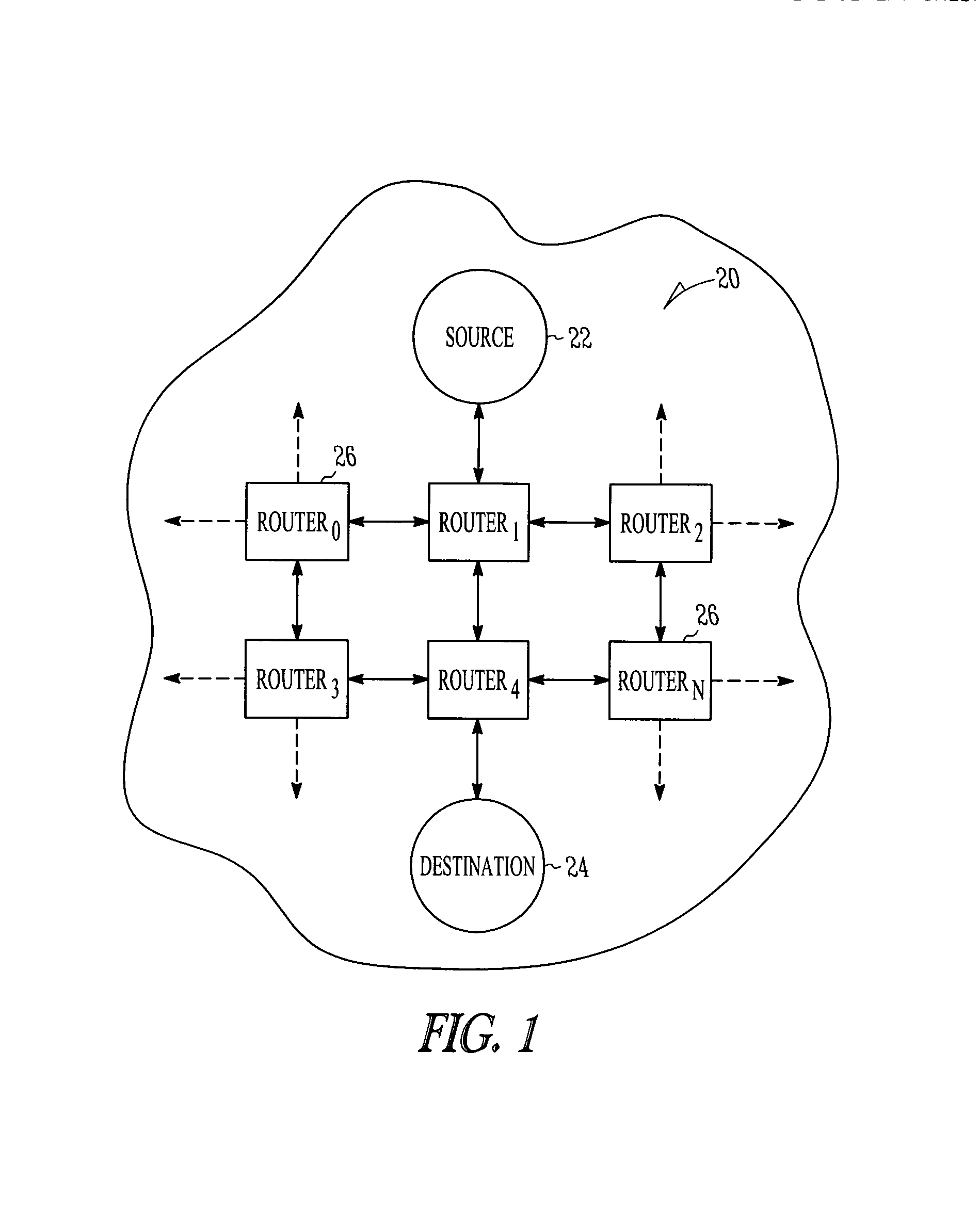
CROSS-REFERENCE TO RELATED APPLICATION[0001]This application is a continuation-in-part of the commonly assigned patent application entitled “PACKET ROUTING AND SWITCHING DEVICE,” filed on Jun. 20, 2002, application Ser. No. 10 / 177,496 now U.S. Pat. No. 7,382,787, the disclosure of which is hereby incorporated by reference in its entirety.FIELD OF THE INVENTION[0002]This invention relates, in general, to network routers, and more particularly to a redundant device and method for performing routing and switching in a packet-switched computer network.BACKGROUND OF THE INVENTION[0003]Computer networks often use packet-switching for transmitting messages, such as web pages and e-mail, along a path between a source and a destination on the network. An example of the basic topology of a packet-switched network 20 is illustrated in FIG. 1, and the Internet is one example of a packet-switched network.[0004]In a packet-switched network, messages to be transmitted are first divided into smalle...

Claims


Application Information

Patent Timeline
Patent Type & Authority Patents(United States)
IPC IPC(8): G06F11/00
CPCH04L12/66H04L49/252H04L49/3072H04L49/552
Inventor LI, ANTHONY J.LYNCH, WILLIAM L.BARNES, PETER M.
Owner CISCO TECH INC
Learn More