
Electrostatic coating of a device

a technology of electrostatic coating and device, which is applied in the direction of prosthesis, catheter, food packaging, etc., can solve the problems of uneven coating, coating, and disadvantages of conventional spray coating methods, which are usually implemented with a device such as an airbrush, and achieve uneven coating of stents

Inactive Publication Date: 2009-04-28
BOSTON SCI SCIMED INC
View PDF20 Cites 74 Cited by
  • Summary
  • Abstract
  • Description
  • Claims
  • Application Information

AI Technical Summary

Problems solved by technology

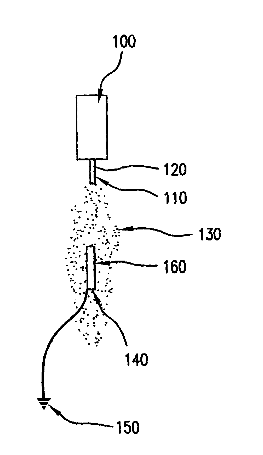
However, the conventional spray-coating methods, which are usually implemented with a device such as an airbrush, have drawbacks.
For example, when a medical device has a structure such that a portion of the device obstructs sprayed droplets from reaching another portion of the device, then the coating becomes uneven.
Hence, conventional spraying methods tend to produce coated stents with coatings that are not uniform.
Furthermore, conventional spraying methods are inefficient.
In particular, generally only 5% of the coating solution that is sprayed to coat the medical device is actually deposited on the surface of the medical device.
The majority of the sprayed coating solution is therefore wasted.
This process also suffers from many inefficiencies including the unevenness of the coated layer and a lack of control over the coated layer's thickness.
One disadvantage of conventional electrostatic spraying is that it requires a complicated spraying apparatus.
However, it is not easy to control the gas pressure so that the target surface is evenly and sufficiently coated without losing much of the coating solution.

Method used


Image

  • Electrostatic coating of a device
  • Electrostatic coating of a device

Examples


Embodiment Construction

[0013]As used herein, the term “therapeutic agent” includes one or more “therapeutic agents” or “drugs” . The terms “therapeutic agents” , “active substance” and “drugs” are used interchangeably herein and include pharmaceutically active compounds, nucleic acids with and without carrier vectors such as lipids, compacting agents (such as histones), virus (such as adenovirus, andenoassociated virus, retrovirus, lentivirus and α-virus), polymers, hyaluronic acid, proteins, cells and the like, with or without targeting sequences.

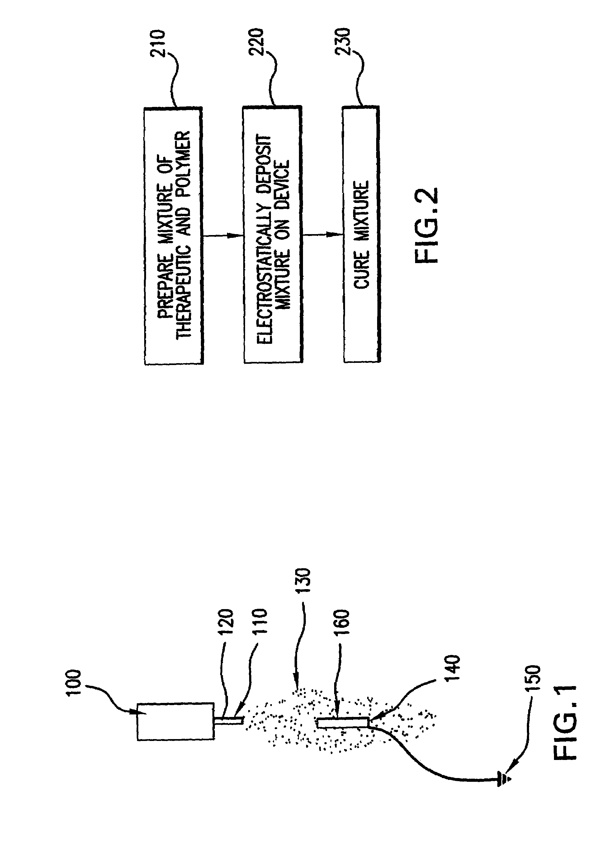
[0014]In one embodiment of the invention, a process for coating a structure such as a stent includes first preparing a mixture of a polymer and an active substance or therapeutic. The mixture may be in the form of a powder. Then, the process includes forming a first coating on the structure by electrostatically depositing the mixture on the structure. This step can be followed by a step to cure the mixture.

[0015]One way to cure the mixture includes forming a sec...


PUM

PropertyMeasurementUnit
Weightaaaaaaaaaa
Freezing pointaaaaaaaaaa

Abstract

The present invention concerns bio-compatible medical devices and process for preparation thereof. The process includes electrostatically forming a first layer on a structure. The first layer can include a combination of at least one active substance and at least one polymer and / or binder. A second layer is formed on the structure to cover the first layer. The second layer can be a solvent or a combination of solvents. The evaporation of the second layer causes the first layer to reflow and bind to the structure.

Description

TECHNICAL FIELD[0001]The present invention relates to the controlled delivery of therapeutic agents to a target site of an organic vessel.BACKGROUND[0002]Medical implants are used for a number of medical purposes, including the reinforcement of recently re-enlarged lumens, the replacement of ruptured vessels, and the treatment of disease such as vascular disease by local pharmacotherapy, i.e., delivering therapeutic drug doses to target tissues while minimizing systemic side effects. Such localized delivery of therapeutic agents has been achieved using medical implants which both support a lumen within a patient's body and place appropriate coatings containing absorbable therapeutic agents at the implant location. Examples of such medical devices include catheters, guide wires, balloons, filters (e.g., vena cava filters), stents, stent grafts, vascular grafts, intraluminal paving systems, implants and other devices used in connection with drug-loaded polymer coatings. Such medical d...

Claims


Application Information

Patent Timeline
IPC IPC(8): B05D1/34A61L27/00B05D1/04A61L31/10A61L31/16
CPCA61L31/10A61L31/16Y10T428/254A61L2420/08A61L2420/02
Inventor STENZEL, ERIC B.
Owner BOSTON SCI SCIMED INC
Learn More