
Variable sensitivity control for a cochlear implant

Active Publication Date: 2009-04-21
COCHLEAR LIMITED
View PDF8 Cites 5 Cited by
  • Summary
  • Abstract
  • Description
  • Claims
  • Application Information

AI Technical Summary

Benefits of technology

[0031]Embodiments of the invention may thus ensure that all input signals which are substantially equal to or above the current estimated noise floor value will be converted to an output signal above or at the hearing threshold value, and accordingly, will be passed to the auditory nerve of a user of an auditory prosthesis incorporating such an amplifier in a perceptible manner. Further, by altering the gain of the amplifier in response to a change in the current estimated noise floor value, or by altering the gain compression ratio, or by altering the dynamic range of the amplifier in response to a change in the current estimated noise floor value, the present invention allows for adaptive operation of the amplifier responsive to varying noise floor levels, while maintaining desired gain characteristics of the amplifier across a range of input signal levels.
[0050]Preferably, the amplifier response is continuous, monotonic and increasing for all output signal levels between the hearing threshold value and the maximum comfort value. The amplifier preferably produces an output signal equal in magnitude to the hearing threshold value when the input signal equals the current estimated noise floor level. Preferably, the gain control means ensures that the amplifier does not produce any output signals which exceed a maximum comfort level, even when the input signal is at high levels. For example, the amplifier may produce a constant output signal level for all input signal levels above a maximum input level. That is, the amplifier may be controlled to enter infinite compression when the input signal goes beyond the maximum input level. The maximum input level could, for example, be in the range 60-90 dB, and could be around 70 dB. The setting of a maximum output level from the amplifying means serves to ensure that no damage is caused to the auditory prosthesis, such as the electrode array of a cochlear implant, and / or avoids discomfort to the user.
[0054]In a preferred embodiment, the amplifying means provides linear gain of input signals which are greater in amplitude than the current estimated noise floor value, and are lesser in amplitude than the input signal level at which the amplifier enters infinite compression.
[0059]In such embodiments, the slope of the amplifier response is preferably greater for smaller input signal levels, and is reduced for input signal levels above the breakpoint or first breakpoint. Hence, input signals such as speech received at levels above the breakpoint will be partially compressed, relative to input signals at a level below the breakpoint. Such compression can improve understanding of speech for cochlear implant users, which may be attributable to the broad dynamic range of the amplifier provided by such embodiments.

Problems solved by technology

These people are thus unable to derive suitable benefit from conventional hearing aid systems, no matter how loud the acoustic stimulus is made, because there is damage to or absence of the mechanism for nerve impulses to be generated from sound in the normal manner.
Strategies that employed this feature extraction philosophy were found to work particularly well when the user was listening to a single voice in a quiet environment, however, when the user was in an environment with background noise the strategy was not nearly as successful.
The result was a signal which the user could not readily understand.
Setting the sensitivity lower results in some of the signal falling outside the stimulation range, and so reducing speech perception.
A problem can occur with this system when a user is faced with an environment where the level of background noise is varying.
Although this system provides improved listening comfort for the user, the system does have the disadvantage that at low speech levels, a step of simply linearly increasing the amount of gain is insufficient to maintain such speech perception at a satisfactory level.

Method used


Image

  • Variable sensitivity control for a cochlear implant
  • Variable sensitivity control for a cochlear implant
  • Variable sensitivity control for a cochlear implant

Examples


Embodiment Construction

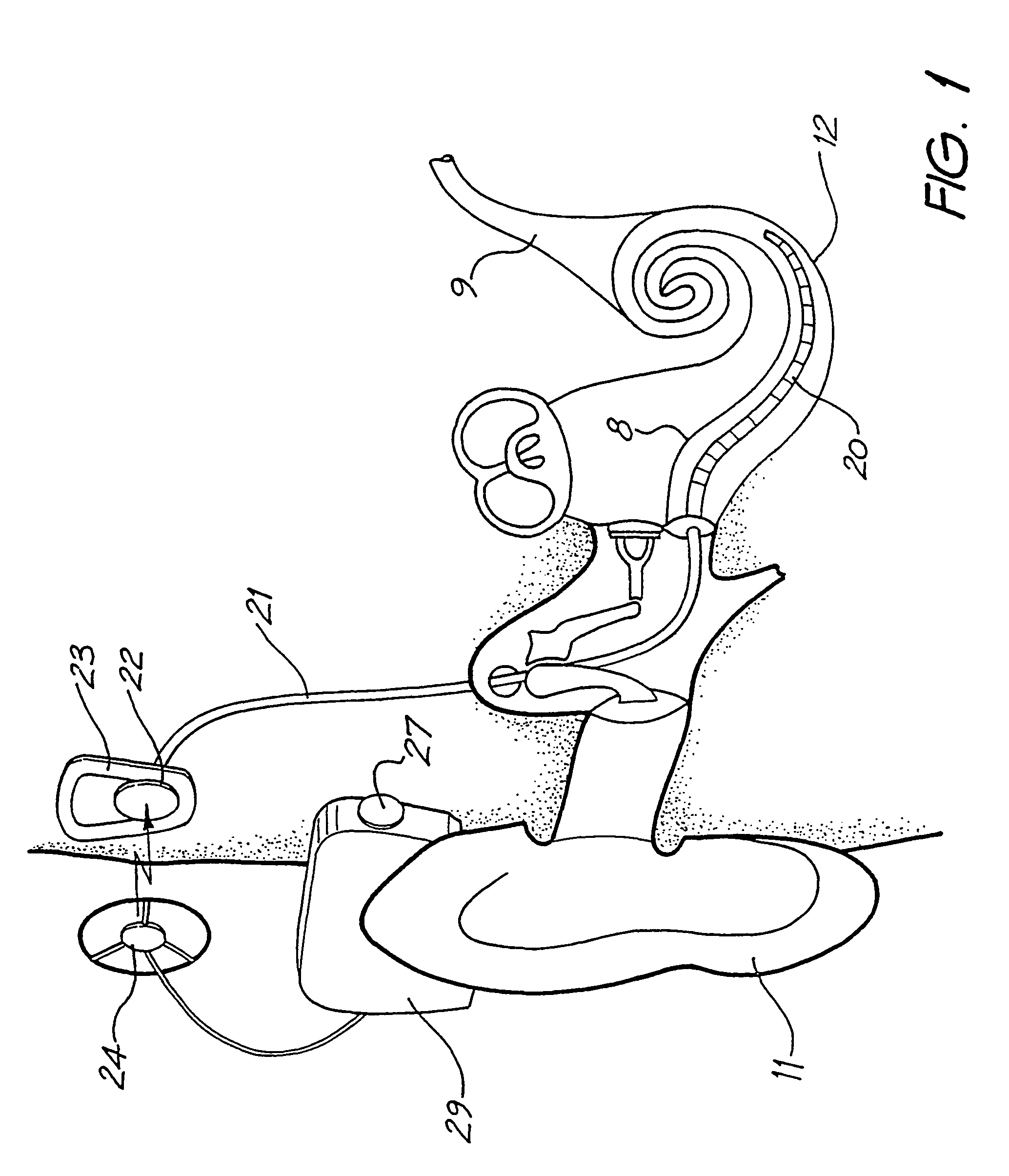
[0076]Before describing the features of the present invention, it is appropriate to briefly describe the construction of one type of known cochlear implant system with reference to FIG. 1.

[0077]Known cochlear implants typically consist of two main components, an external component including a speech processor 29, and an internal component including an implanted receiver and stimulator unit 22. The external component includes an on-board microphone 27. The speech processor 29 is, in this illustration, constructed and arranged so that it can fit behind the outer ear 11. Alternative versions may be worn on the body. Attached to the speech processor 29 is a transmitter coil 24 which transmits electrical signals to the implanted unit 22 via an RF link.

[0078]The implanted component includes a receiver coil 23 for receiving power and data from the transmitter coil 24. A cable 21 extends from the implanted receiver and stimulator unit 22 to the cochlea 12 and terminates in an electrode arra...


PUM


Abstract

The invention provides an amplifier for providing adaptive operation of an auditory prosthesis. The amplifier receives an input signal and produces an output signal, and comprises a gain control. Estimates of the current noise floor value of the input signal are obtained, and in response to a change in the current estimated noise floor value, the gain control alters the amount of gain applied to the input signal. Further, in response to the change in the current estimated noise floor value, the gain control alters a gain compression ratio of the amplifier across the dynamic range of the amplifier. The present invention allows for adaptive operation of the amplifier responsive to varying noise floor levels, while maintaining desired gain characteristics of the amplifier across a range of input signal levels.

Description

CROSS-REFERENCE TO RELATED APPLICATION[0001]This application is a National Phase Patent Application of International Application Number PCT / AU02 / 00463, filed on 11 Apr. 2002, which claims priority of Australian Patent Application No. PR 4386, filed 11 Apr. 2001.TECHNICAL FIELD[0002]The present invention relates to a method and device for controlling the sensitivity and gain of an amplifier used in a hearing device, such as a hearing aid or cochlear implant.BACKGROUND ART[0003]In many people who are profoundly deaf, the reason for deafness is absence of, or destruction of, the hair cells in the cochlea which transduce acoustic signals into nerve impulses. These people are thus unable to derive suitable benefit from conventional hearing aid systems, no matter how loud the acoustic stimulus is made, because there is damage to or absence of the mechanism for nerve impulses to be generated from sound in the normal manner.[0004]It is for this purpose that cochlear implant systems have bee...

Claims


Application Information

Patent Timeline
IPC IPC(8): A61N1/00H04R25/00
CPCH04R25/606H04R25/356
Inventor SELIGMAN, PETER MISHAMCDERMOTT, HUGH
Owner COCHLEAR LIMITED
Learn More