
Oil monitoring system

a monitoring system and oil technology, applied in the direction of resistance/reactance/impedence, measurement devices, instruments, etc., can solve the problems of inconvenient ‘on-the-fly’ testing, complex determination of oil quality, and inducing vibrational excitation of covalently bonded atoms and groups

Inactive Publication Date: 2009-04-21
VOELKER SENSORS
View PDF31 Cites 30 Cited by
  • Summary
  • Abstract
  • Description
  • Claims
  • Application Information

AI Technical Summary

Benefits of technology

This approach enables accurate, real-time monitoring of oil quality, differentiating between oil additives and base oil properties, and detecting contaminants, thus providing a more reliable indication of oil condition and need for replacement, reducing the risk of engine damage from degraded oil.

Problems solved by technology

Determining oil quality is a complex issue.
These photon energies may, however, induce vibrational excitation of covalently bonded atoms and groups.
In addition to being expensive, this methodology is not conducive to ‘on-the-fly’ testing.
Absent infrared spectrometers being introduced as standard equipment in automobiles and other machines that utilize natural and synthetic oils, infrared spectroscopy cannot be utilized to provide instantaneous indications of oil quality and / or that oil needs to be changed.
While the pH of oil provides an indication of changes in acidity or causticity with regard to the presence (or absence) of certain acids, pH does not measure oil lubricating quality.
Further, pH measurements do not determine if the oil has degraded due to foreign particles and contaminants such as water or metal particulate.
Additionally, pH measurements can be skewed by the presence of volatile acids that evaporate over time at certain operating temperatures.
The presence and / or subsequent evaporation of those acids can provide a false and / or inconsistent pH reading that is not relative to the actual quality of the oil being measured.
A pH sensor apparatus, too, is expensive and not particularly suited for the environment of the oil pan of an internal combustion engine.
The timing of the indicia of replacement (e.g., the activation of a dashboard warning light) is based on the prediction of degradation and that the oil is no longer providing particular performance guarantees as governed by the quality of the oil.
This methodology, however, does not take into account the various qualities or quantities of oil that may be used in a particular vehicle.
This methodology further fails to account for the particularities of the engine operating environment (e.g., engine wear independent of the oil quality) in addition actual driving conditions (e.g., city or highway, summer or winter, and so forth).
This methodology, in addition to its overall inaccuracy, provides no qualitative or quantitative information regarding oil condition in that the indicia of the need for oil replacement is purely binary (i.e., time-to-change or not time-to-change).
The presence of contaminates will further increase or decrease the viscosity of a particular oil sample thereby hampering measurement.
Increased polarity causes the oil to change is dielectric constant, which in turn leads to increased capacitance.
Oil deterioration also results in a decrease of additives.
As the dielectric constant of the oil becomes greater than that of the additives in the oil, useful direct oil analysis becomes difficult if not impossible.
While a variety of means are known in the art to measure oil pressure, there is a general lack of means to accurately and effectively measure oil quality.
Those sensors that do exist often encounter the aforementioned problem of differentiating increases in oil dielectric constant versus presence and quality of oil additives.

Method used


Image

  • Oil monitoring system
  • Oil monitoring system
  • Oil monitoring system

Examples


Embodiment Construction

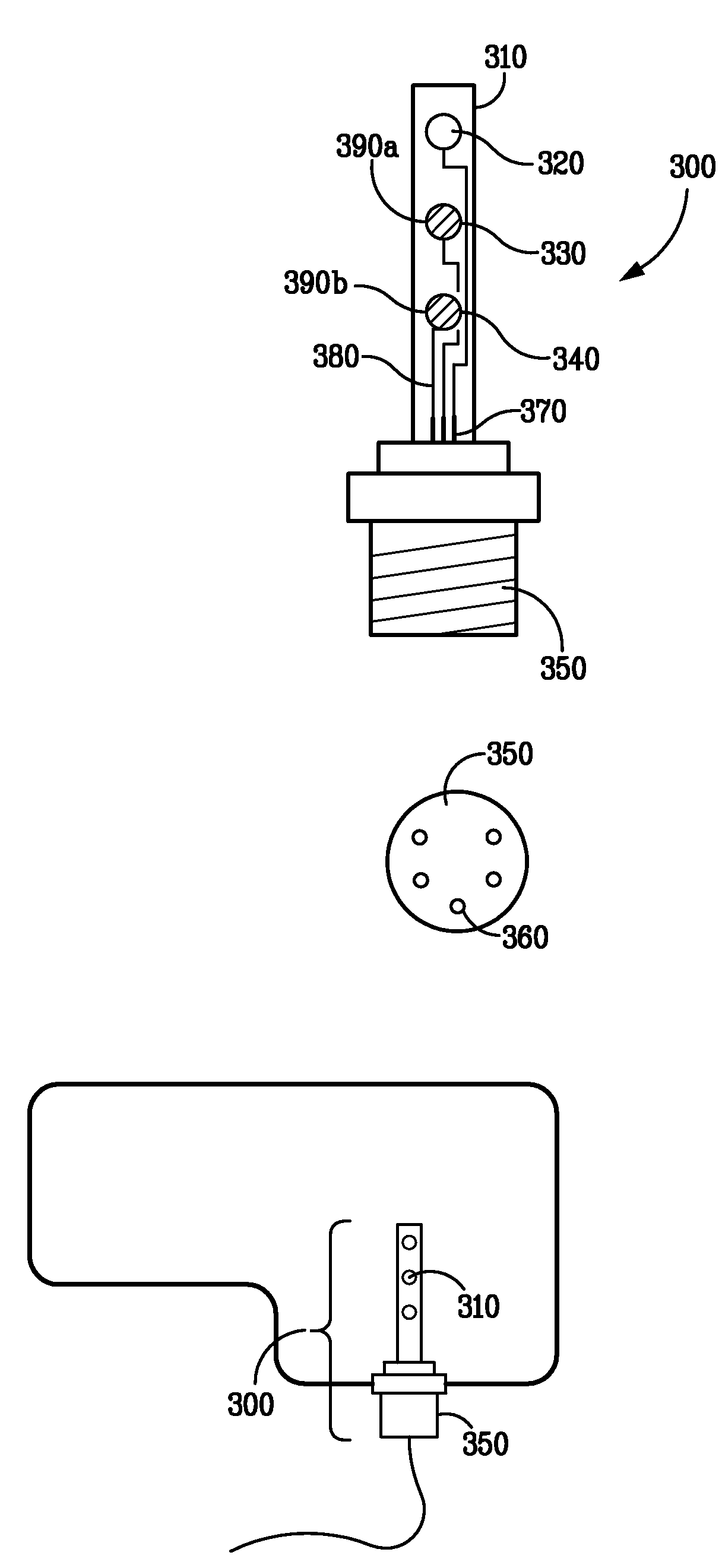
[0035]FIG. 2 illustrates an exemplary real-time oil monitoring system 200 as may be implemented in accordance with an embodiment of the present invention. An embodiment of the oil monitoring system 200 may comprise a monitoring device 210 for receiving and analyzing data generated by a sensing element 220, which is in contact with the oil or other fluid under observation.

[0036]Data generated by the sensing element 220 may be communicated to the monitoring device 210 via a sensor signal cable 230. Sensor signal cable 230, in one embodiment of the present invention, is an RS-232 compliant serial cable wherein one end of the cable is configured to exchange data with the monitoring device 210 and the opposite end of the cable is configured to interface with sensing element 220 as is discussed in greater detail in FIG. 3. Other data cables are within the scope of the present invention subject to proper configuration to allow for interface with the sensing element 220 and monitoring devic...


PUM

PropertyMeasurementUnit
operating temperaturesaaaaaaaaaa
diameteraaaaaaaaaa
alternating currentaaaaaaaaaa

Abstract

An embodiment of the present invention provides for a sensing element comprising a non-conductive housing with three chambers for detecting oil conductivity, additive depletion and oxidation, and water contamination, respectively. Through the monitoring of an array of oil sensors, an early warning of oil degradation due to oxidation is provided. The monitoring system further detects excess soot, water and other contaminants in the oil. The oil sensor array and related monitoring system decrease the likelihood of catastrophic engine failure through the early detection and warning of a decrease in oil quality thereby reducing vehicle owner outlays for servicing and disposal fees while further aiding in the satisfaction of environmental protection regulations.

Description

CROSS-REFERENCE TO RELATED APPLICATIONS[0001]The present application claims the priority benefit of U.S. provisional patent application No. 60 / 774,749 filed Feb. 17, 2006 and entitled “Oil Sensor” and U.S. provisional patent application No. 60 / 782,959 filed Mar. 15, 2006 and entitled “Oil Monitoring System with Oil Sensing Element.” The disclosure of both applications is incorporated herein by reference.[0002]The present application is related to U.S. Pat. No. 5,435,170, entitled “Method and Apparatus for Fluid Quality Sensing”; U.S. Pat. No. 5,777,210, entitled “Oil Quality Sensor Measuring Bead Volume”; and U.S. Pat. No. 5,789,665 entitled “Oil Quality Sensor for Use in a Motor Oil.” The disclosure of these commonly owned patents is incorporated herein by reference.BACKGROUND OF THE INVENTION[0003]1. Field of the Invention[0004]The present invention relates generally to measurement and testing for liquid analysis. More specifically, the present invention relates to the analysis of...

Claims


Application Information

Patent Timeline
Patent Type & Authority Patents(United States)
IPC IPC(8): G01R27/08G01N33/26
CPCG01N33/2888
Inventor HEDGES, JOE D.VOELKER, PAUL J.
Owner VOELKER SENSORS
Learn More