Eureka AIR delivers breakthrough ideas for toughest innovation challenges, trusted by R&D personnel around the world.

Semiconductor optical modulator

a semiconductor and optical modulator technology, applied in the field of optical communication, can solve the problems of modulator chirping degrading certain transmission qualities of modulated light, modulator chirping exhibiting index-change-dependent waveguide loss, etc., to reduce the effect of optical index change, reducing propagation loss changes, and minimizing chirp

Active Publication Date: 2009-04-14
ALCATEL-LUCENT USA INC
View PDF5 Cites 3 Cited by
  • Summary
  • Abstract
  • Description
  • Claims
  • Application Information

AI Technical Summary

Benefits of technology

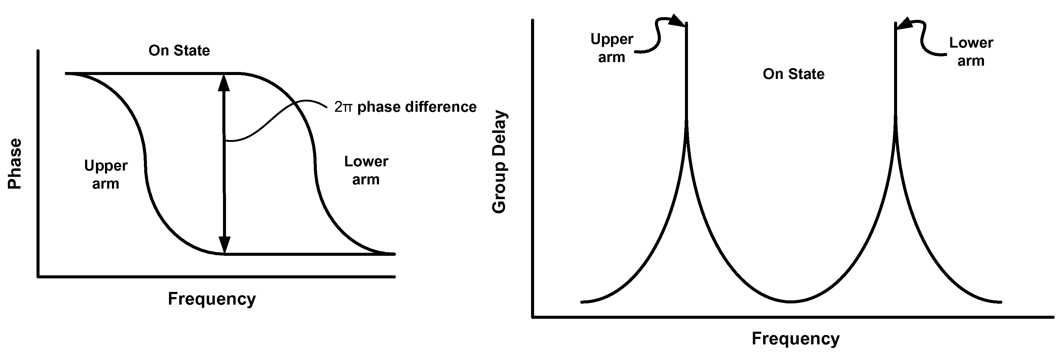
[0007]In accordance with an aspect of the present invention, each of the resonators exhibits a particular resonance that substantially overlaps one another when the modulator is turned off and have less overlap when the modulator is turned on. In sharp contrast to prior art configurations, this configuration advantageously reduces any required optical index changes which, in turn, reduces changes in propagation losses experienced in, for example, carrier injected silicon waveguide structures thereby minimizing the chirp.
[0008]In accordance with yet another aspect of the invention, an optical modulator so constructed may advantageously produce differential phase shift keying (DPSK) and higher order advanced modulation formats with minimal chirp.

Problems solved by technology

Unfortunately, chirping degrades certain transmission qualities of modulated light.
In addition, Si modulators exhibit a waveguide loss that is dependent upon refractive index change.
Modulators exhibiting such index-change-dependent waveguide loss are unsuitable for use with many modulation formats that are used in advanced optical communications systems.

Method used


Image

  • Semiconductor optical modulator
  • Semiconductor optical modulator
  • Semiconductor optical modulator

Examples


Embodiment Construction

[0023]The following merely illustrates the principles of the invention. It will thus be appreciated that those skilled in the art will be able to devise various arrangements which, although not explicitly described or shown herein, embody the principles of the invention and are included within its spirit and scope.

[0024]Furthermore, all examples and conditional language recited herein are principally intended expressly to be only for pedagogical purposes to aid the reader in understanding the principles of the invention and the concepts contributed by the inventor(s) to furthering the art, and are to be construed as being without limitation to such specifically recited examples and conditions.

[0025]Moreover, all statements herein reciting principles, aspects, and embodiments of the invention, as well as specific examples thereof, are intended to encompass both structural and functional equivalents thereof. Additionally, it is intended that such equivalents include both currently kno...


PUM

PropertyMeasurementUnit
resonance frequencyaaaaaaaaaa
resonance frequenciesaaaaaaaaaa
phaseaaaaaaaaaa

Abstract

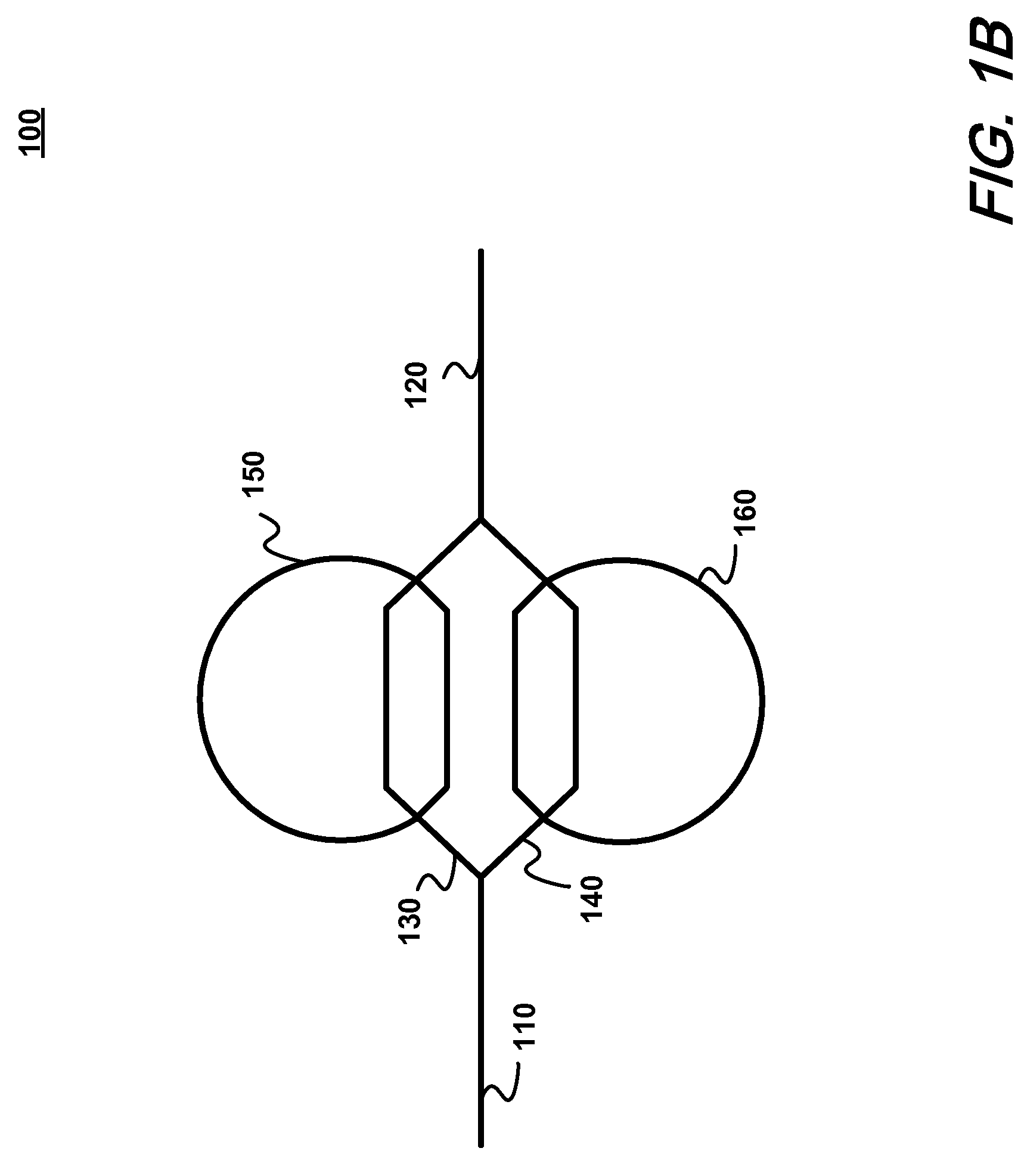
Semiconductor optical modulator devices exhibiting improved chirp characteristics are constructed from a Mach-Zehnder structure having resonators positioned within each arm and a number of phases shifters positioned within the arms, and / or resonators.

Description

UNITED STATES GOVERNMENT INTEREST[0001]The United States Government has a paid-up license in this invention and the right in limited circumstances to require the patent owner to license others on reasonable terms as provided for the by the terms of contract No. HR0011-05-C-0027 awarded by the Defense Research Project Agency.FIELD OF THE INVENTION[0002]This invention relates generally to the field of optical communications and in particular to optical modulators exhibiting improved chirp characteristics.BACKGROUND OF THE INVENTION[0003]Optical modulators constructed from Si or other semiconductor materials may impart certain phase changes or “chirp” to optical signals upon which they operate. Unfortunately, chirping degrades certain transmission qualities of modulated light.[0004]In addition, Si modulators exhibit a waveguide loss that is dependent upon refractive index change. Modulators exhibiting such index-change-dependent waveguide loss are unsuitable for use with many modulatio...

Claims


Application Information

Patent Timeline
Patent Type & Authority Patents(United States)
IPC IPC(8): G02B6/26G02B26/00G02B6/42G02F1/03G02F1/035G02F1/07G02F1/295
CPCG02F1/225G02F1/2257G02F2001/212G02F2203/15G02F1/212
Inventor GILL, DOUGLASRASRAS, MAHMOUD
Owner ALCATEL-LUCENT USA INC
Why Eureka
Eureka Blog
Learn More