
LED lamp having heat sink

Inactive Publication Date: 2009-04-07
FU ZHUN PRECISION IND SHENZHEN +1
View PDF5 Cites 156 Cited by
  • Summary
  • Abstract
  • Description
  • Claims
  • Application Information

AI Technical Summary

Benefits of technology

[0008]What is needed, therefore, is an LED lamp which has a heat sink with a great heat dissipating capability in a limited space. Furthermore, the heat sink applied in the LED lamp has a special design, whereby the LED lamp can provide an illumination area with an even brightness and no shadow therein.

Problems solved by technology

Most of the LEDs are driven at the same time, which results in a quick rise in temperature of the LED lamp.
Since the limited space in the LED lamp, the heat sink has a restricted heat dissipating area and is unable to remove heat from the LEDs effectively.
Operation of the conventional LED lamps thus has a problem of instability because of the rapid buildup of heat.
Besides, since an illumination angle of the light emitted by the LEDs of the conventional lamp is restricted to a radially outward direction of the heat sink, a shadow is generated at a center of the illumination region of the conventional LED lamp, which significantly reduces the usefulness of the conventional LED lamp.

Method used


Image

  • LED lamp having heat sink
  • LED lamp having heat sink
  • LED lamp having heat sink

Examples


Embodiment Construction

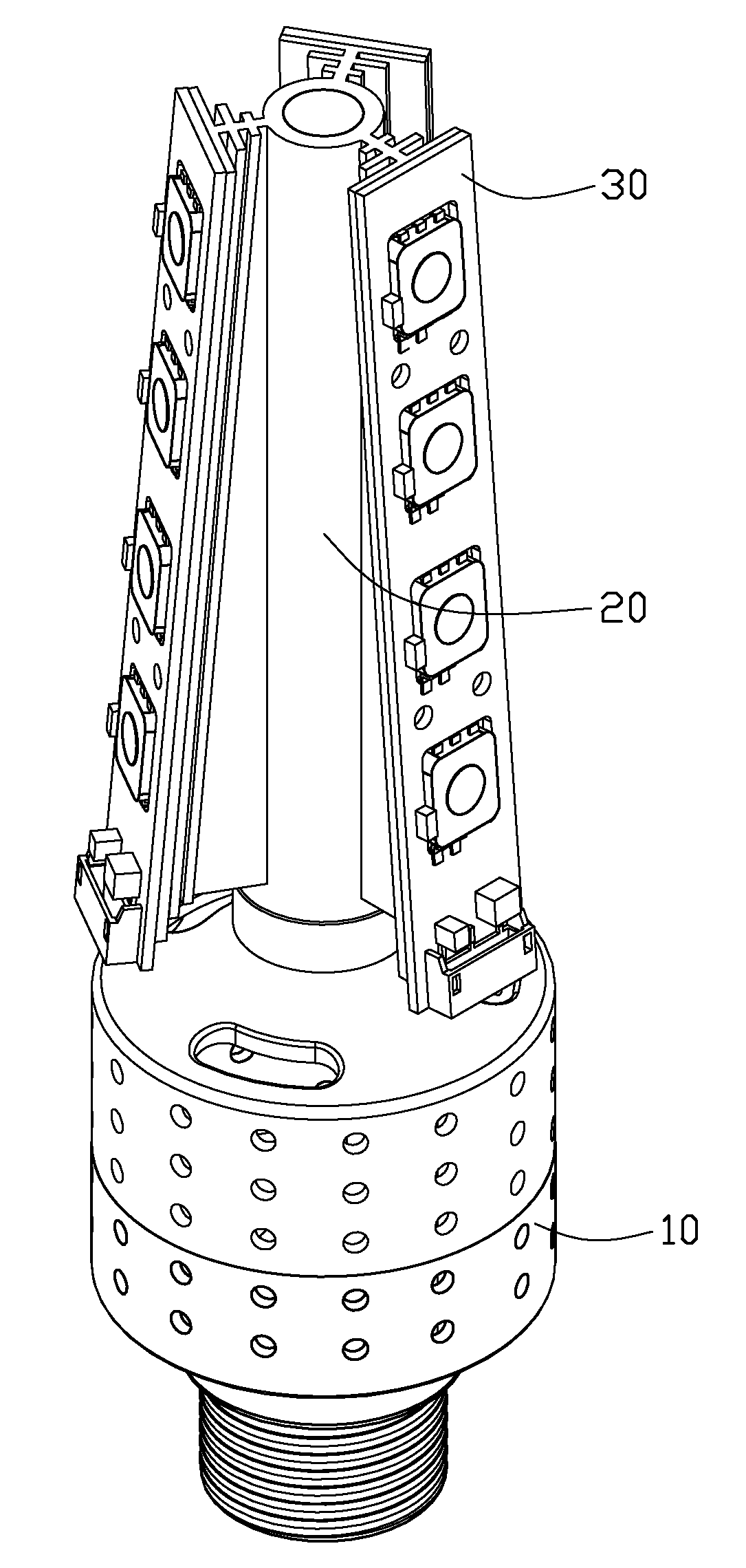
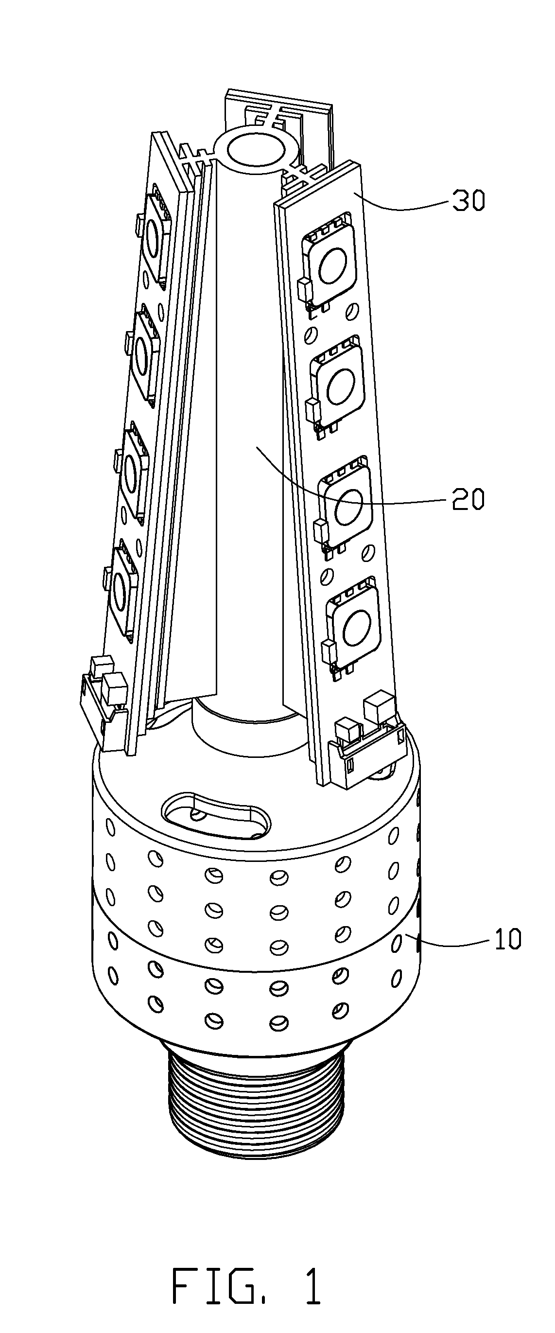
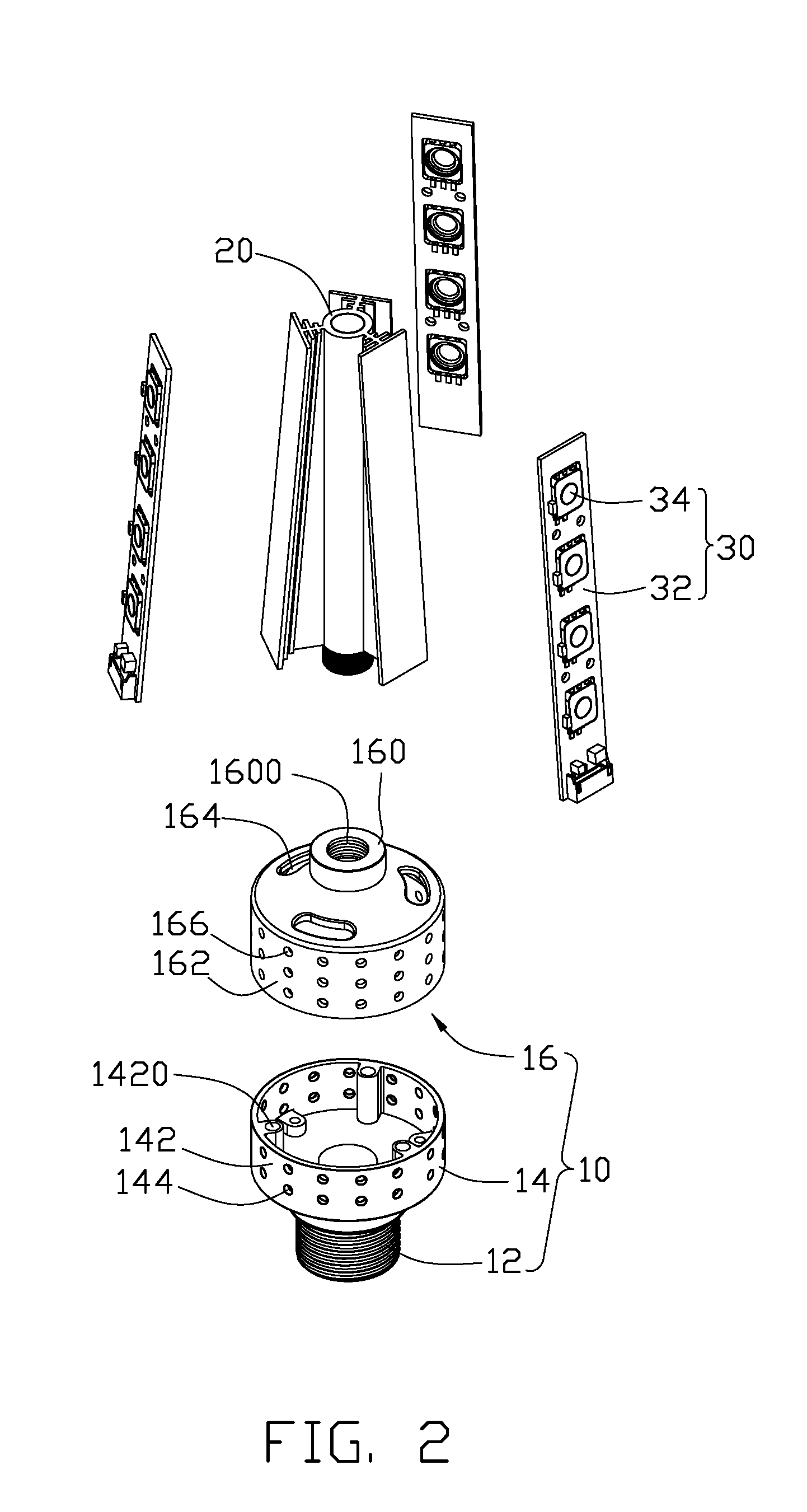
[0015]Referring to FIGS. 1-2, an LED lamp for a lighting purpose comprises a lamp base 10, a heat sink 20 coupled to the lamp base 10 and a plurality of LED modules 30 thermally attached to a periphery of the heat sink 20.

[0016]The lamp base 10 comprises a lamp holder 12, a first cover 14 connecting with the lamp holder 12 and a second cover 16 facing to and engaging with the first cover 14. The lamp holder 12 has screw threads formed on a periphery thereof and has a standardized configuration for fitting in a standardized lamp socket (not shown). The first cover 14 comprises a cone-shaped joining portion (not labeled) coupled with the lamp holder 12 and a first bowl-shaped body 142 extending upwardly from an upper edge of the joining portion. The first bowl-shaped body 142 which has a constant caliber is substantially tube-shaped and symmetrically defines a plurality of vents 144 therein. Three fixing orifices 1420 are evenly defined in an inner rim of the first bowl-shaped body 14...


PUM


Abstract

An LED lamp includes a lamp base, a heat sink mounted on the lamp base and a plurality of LED modules thermally contacting with the heat sink. The lamp base defines a plurality of vents therein. The heat sink includes a central cylinder and a plurality of fins spaced from and surrounding the cylinder. The cylinder defines a through hole therein, which communicates with the vents of the lamp base and cooperates with the vents to form an air passage communicating with ambient air. An included angle is defined between each of the fins and a central axis of the cylinder. The LED modules are mounted on outmost ones of the fins of the heat sink, respectively.

Description

BACKGROUND OF THE INVENTION[0001]1. Field of the Invention[0002]The present invention relates to an LED lamp, and particularly to an LED lamp having a heat sink for dissipating heat from LEDs of the LED lamp.[0003]2. Description of Related Art[0004]Electronic component includes numerous circuits operating at high speed and generating substantive heat. In many applications, it is desirable to employ a heat sink to remove heat from heat-generating electronic components, for example, LED components in an LED lamp, to assure that the components function properly and reliably.[0005]An LED lamp is a type of solid-state lighting device that utilizes light-emitting diodes (LEDs) as a source of illumination. An LED is a device for converting electricity into light by using a theory that, if a current is made to flow in a forward direction through a junction region comprising two different types of semiconductor, electrons and holes are coupled at the junction region to generate a light beam....

Claims


Application Information

Patent Timeline
IPC IPC(8): F21V29/00
CPCF21V29/004F21K9/135F21V29/83F21V29/76F21V29/75F21Y2101/02F21Y2111/005F21Y2111/007H01L2924/0002H01L2924/00F21K9/232F21Y2115/10F21Y2107/30F21Y2107/40F21V23/001F21V29/74
Inventor LIU, JUNCHEN, YONG-DONGWUNG, SHIH-HSUN
Owner FU ZHUN PRECISION IND SHENZHEN
Learn More