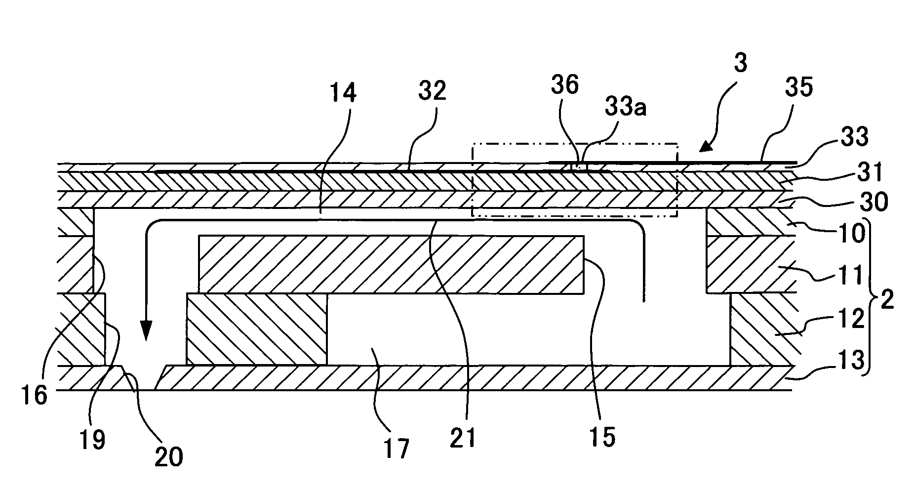
Piezoelectric actuator, liquid transporting apparatus, and method of producing piezoelectric actuator

a technology of actuators and actuators, which is applied in the direction of generators/motors, instruments, generators, etc., can solve the problems of low reliability of electric connections between individual electrodes and wiring members, high cost of wiring members, and exfoliation of wiring members, so as to improve the structure of electric connections for supplying drive voltage to individual electrodes, improve the reliability of electric connections, and improve the effect of electric connection reliability

Active Publication Date: 2009-03-31
BROTHER KOGYO KK
View PDF18 Cites 6 Cited by
  • Summary
  • Abstract
  • Description
  • Claims
  • Application Information

AI Technical Summary

Benefits of technology

[0011]An object of the present invention is to provide a piezoelectric actuator which can realize both of the simplification of structure of electric connections for applying the drive voltage to the piezoelectric layer and the improvement in reliability of the electric connections, and which is capable of further suppressing the generation of excessive electrostatic capacitance when the drive voltage is applied, a method of producing the piezoelectric actuator, and a liquid transporting apparatus in which the piezoelectric actuator is used.
[0027]In the method of producing the piezoelectric actuator of the present invention, the filling step and the wiring forming step may be performed simultaneously. According to the method of producing the piezoelectric actuator, since it is possible to form the wirings while filling the electroconductive material in the first through hole, it is possible to simplify the producing process.

Problems solved by technology

US2004 / 119790 A1, since it is necessary to form, in high density, a wiring pattern of the wiring member which is connected to the land portions of the individual electrodes, a cost of the wiring member becomes high.
Moreover, since contact portions of the wiring member is connected to each of the land portions with a wiring member such as the FPC is arranged to cover the land portions of the individual electrodes arranged flatly, when an external force acts on the wiring member, the wiring member tends to be exfoliated, and a reliability of electric connections between the individual electrodes and the wiring member is low.
Accordingly, the cost of the flexible printed circuit becomes high.
Furthermore, since the ink-jet head and the flexible printed circuit are connected only at portions between the head terminals of the ink-jet head and the corresponding land terminals of the flexible printed circuit, there involves a problem that when an external force acts on the flexible printed circuit, the flexible printed circuit tends to be exfoliated.
And, at this time, excessive electrostatic capacitance is generated in the piezoelectric layer at the displacement area which directly contacts with the wirings to which the electric voltage is applied.

Method used


Image

  • Piezoelectric actuator, liquid transporting apparatus, and method of producing piezoelectric actuator
  • Piezoelectric actuator, liquid transporting apparatus, and method of producing piezoelectric actuator
  • Piezoelectric actuator, liquid transporting apparatus, and method of producing piezoelectric actuator

Examples


first modified embodiment

[0083]In the second embodiment, the plurality of through holes 73a (first through holes) are formed in the insulating layer 73 only at the area facing the broad end portion 75a of one of the wirings 75. As shown in FIGS. 15 and 16, however, a plurality of through holes 73b (second through holes) may be formed in an insulating layer 73A even at an area which does not face one of the wirings 75 but faces one of the pressure chambers 14. Thus, by forming the plurality of through holes 73b even at the area not facing one of the wirings 75, the insulating layer 73A becomes even more easily to be deformed, and the deformation of the piezoelectric layer 31 is hardly obstructed by the insulating layer 73A. As a matter of course, unlike the through holes 73a formed at the area facing one of the wirings 75, the electroconductive material 76 is not filled in the plurality of through holes 73b formed at the area not facing one of the wiring 75.

second modified embodiment

[0084]As shown in FIGS. 17 and 18, one through hole 73c which has a large diameter and an opening area substantially equal to an area of the end portion 75a may be formed in an insulating layer 73B at an area facing the broad end portion 75a of one of the wirings 75, and an electroconductive material 76B may be filled in this large diameter through hole 73c. In this case, a contact area of the electroconductive material 76B and the piezoelectric layer 31 becomes wider than the contact area in the second embodiment. Therefore, the voltage can be applied even more assuredly to the piezoelectric layer 31.

third modified embodiment

[0085]Moreover, a modification similar to the modifications made in the first embodiment (the embodiment in which the conducting portion of the driver IC and the vibration plate 30 is formed on the side surfaces of the insulating layer and the piezoelectric layer (see FIG. 9); the embodiment in which the common electrode 34 is provided separately from the vibration plate 30 (see FIG. 10)) can be made in the second embodiment.

[0086]The embodiments in which the present invention is applied to the ink-jet head are explained with the examples of the first embodiment and the second embodiment. However, embodiments to which the present invention is applicable are not limited to the first embodiment and the second embodiment. For example, it is also possible to apply the present invention to various liquid transporting apparatuses which transport liquids other than ink.


PUM


Abstract

A piezoelectric actuator includes a vibration plate covering pressure chambers and serving also as a common electrode, a piezoelectric layer arranged entirely on the upper surface of the vibration plate, an insulating layer formed entirely on upper surfaces of individual electrodes and the piezoelectric layer, and wirings formed on the upper surface of the insulating layer. A through hole is formed in the insulating layer at an area facing both one of the individual electrodes and one of the wirings, and the individual electrode and the wiring are connected by an electroconductive material filled in the through hole. With this, both the simplification of structure of electric contact and the improvement in reliability of electric connection can be realized, and a piezoelectric actuator is capable of suppressing the generation of excessive electrostatic capacitance during the application of drive voltage can be provided.

Description

BACKGROUND OF THE INVENTION[0001]1. Field of the Invention[0002]The present invention relates to a piezoelectric actuator for a liquid transporting apparatus which transports a liquid, a liquid transporting apparatus provided with a piezoelectric actuator, and a method of producing piezoelectric actuator.[0003]2. Description of the Related Art[0004]An ink-jet head which discharges ink from nozzles onto a recording medium such as a recording paper is an example of a liquid transporting apparatus which transports a liquid by applying pressure to the liquid. Such an ink-jet head includes a piezoelectric actuator which is arranged on one surface of a channel unit provided with a plurality of pressure chambers communicating with the nozzles respectively, and which changes selectively volume of the pressure chambers (see, for example, U.S. Patent Application Publication No. US2004 / 119790 A1 corresponding to Japanese Patent Application Laid-open Publication No. 2004-136668; U.S. Pat. Nos. ...

Claims


Application Information

Patent Timeline
Patent Type & Authority Patents(United States)
IPC IPC(8): H04R7/00
CPCB41J2/14233B41J2002/14491B41J2002/14266
Inventor SUGAHARA, HIROTO
Owner BROTHER KOGYO KK
Why Eureka
Try Eureka