Windage insensitive disk drive suspension

Active Publication Date: 2009-03-31
MAGNECOMP
View PDF12 Cites 2 Cited by
  • Summary
  • Abstract
  • Description
  • Claims
  • Application Information

AI Technical Summary

Benefits of technology

[0008]The efforts described above to move the frequencies of the amplitude peaks, or eliminate or reduce their amplitudes helps to reduce the total error. But heretofore left unaddressed has been the portion of the error from non-resonant response of the suspension to windage, represented by the area under the windage function curve between the peaks. Thus even with removal of the peaks there is a substantial area of the curve that represents a source of off track error that has not been reduced.
[0009]The present invention addresses this source of error by reducing the influence of non-resonant response by blocking contact of the airflows with suspension beam portion features that produce error from their interaction with windage. The invention further preferably uses a curvilinear, not straight sided, monocoque configuration that allows a rigid, low mass structure which, when combined with other features of the invention, produces suspensions with responses (natural frequencies of oscillation) that are high enough and amplitudes that are low enough that they are usable in high performance disk drives.

Problems solved by technology

Thus even with removal of the peaks there is a substantial area of the curve that represents a source of off track error that has not been reduced.

Method used


Image

  • Windage insensitive disk drive suspension
  • Windage insensitive disk drive suspension
  • Windage insensitive disk drive suspension

Examples


Embodiment Construction

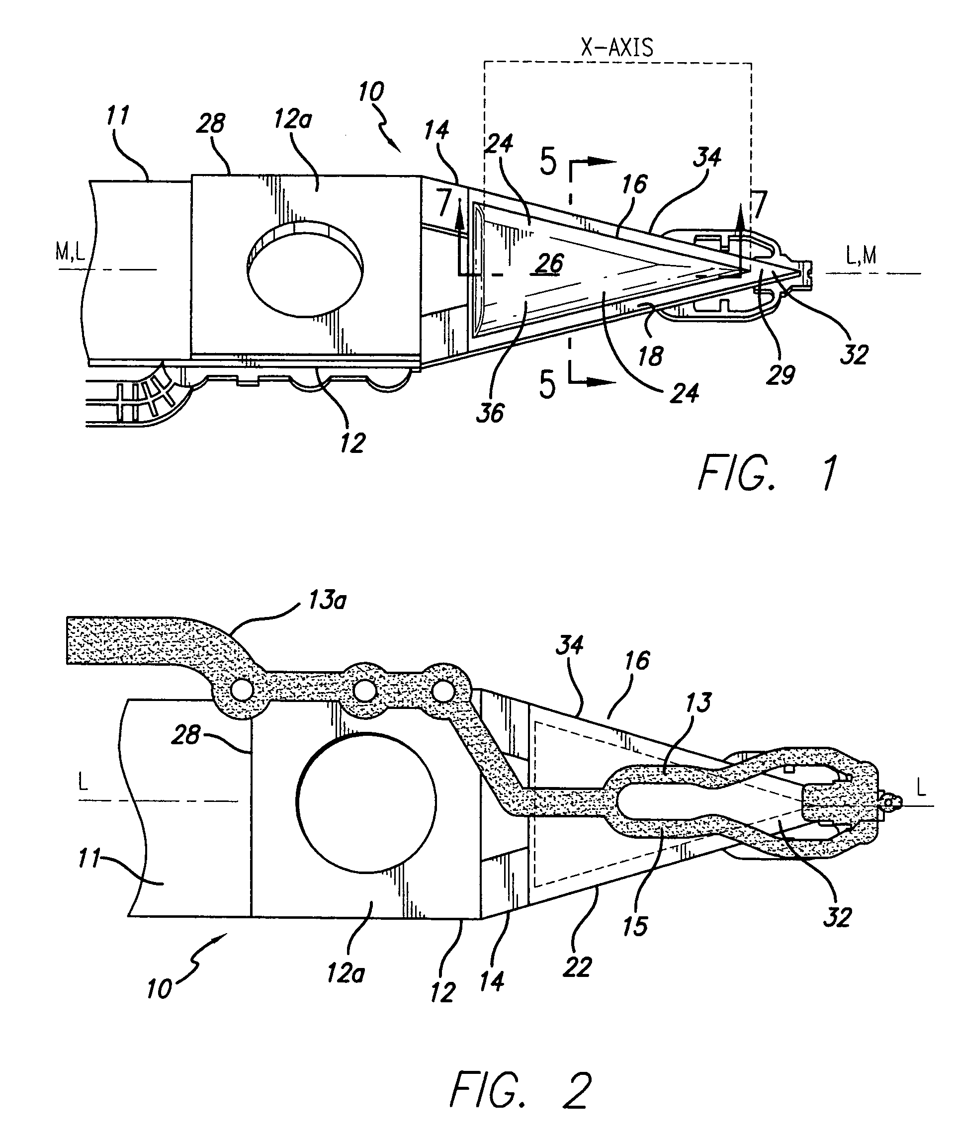
[0058]Disk drive suspensions comprise one or more layers of spring materials such as stainless steel extended horizontally from the actuator and mount plate at the base or proximate end to the gimbal region at the distal end where the slider is mounted. Surface features such as tooling and guide holes for manufacturing convenience, holes for weight reduction, material folds and thickness variations for rigidifying the beam, and weld points are located on the typical suspension in order to meet design criteria for stiffness, mass and dynamics. The presence of these and other protuberant or recessed surface features creates opportunities for windage contacts during suspension flying and these contacts cause windage disturbances and non-resonant frequency vibration modes in the suspension, individually and collectively referred to herein as perturbations of the suspension that lead to TMR, an unstable system and possible loss or miswriting of data.

[0059]This invention seeks to reduce o...


PUM


Abstract

Windage is the sum of multifarious airflows induced and endured inside a disk drive. The invention provides a disk drive suspension and method for use in windage conditions within a disk drive. The suspension has a base portion carrying a hinge portion that carries a beam portion having oppositely facing first and second surfaces. The second surface supports a flexible circuit. Where the beam portion first surface has surface features inducing tracking error-causing perturbations of the beam portion from windage contact with the features, an airfoil profile-defining deflector is provided in operative association with the beam portion to block windage contact with those features and eliminate track misregistration error caused by interaction of the windage and the features.

Description

CROSS-REFERENCE TO RELATED APPLICATIONS[0001]This application claims the benefit of U.S. Provisional Application Ser. No. 60 / 677,225, filed May 2, 2005.BACKGROUND OF THE INVENTION[0002]1. Field of the Invention[0003]This invention relates to disk drive suspensions insensitive to windage encountered in a disk drive that produces track misregistration (TMR) errors. More particularly, the invention relates to disk drive suspensions provided with curvilinear covers over windage sensitive features to provide suspensions having reduced track misregistration errors caused by windage within the disk drive. Windage is the combination of airflow factors acting on a suspension as hereinafter explained. The invention suspension and method block windage airflows from contact with suspension beam surface features that, in windage contact, induce tracking error-causing perturbations in the suspension. The invention uses an airfoil profile-defining deflector that overlies the beam surface features ...

Claims


Application Information

Patent Timeline
IPC IPC(8): G11B21/08
CPCG11B5/4833
Inventor CUEVAS, RAFAEL
Owner MAGNECOMP
Why Eureka
Try Eureka