
Ultra-compact, high-performance motor controller and method of using same

a high-performance, motor controller technology, applied in the direction of programme control, dynamo-electric converter control, coupling device connection, etc., can solve the problems of ultra-compact circuits, ground and connectors, and achieve the effect of enhancing power efficiency and minimizing inductan

Inactive Publication Date: 2009-03-31
BARRETT TECH LLC
View PDF48 Cites 64 Cited by
  • Summary
  • Abstract
  • Description
  • Claims
  • Application Information

AI Technical Summary

Benefits of technology

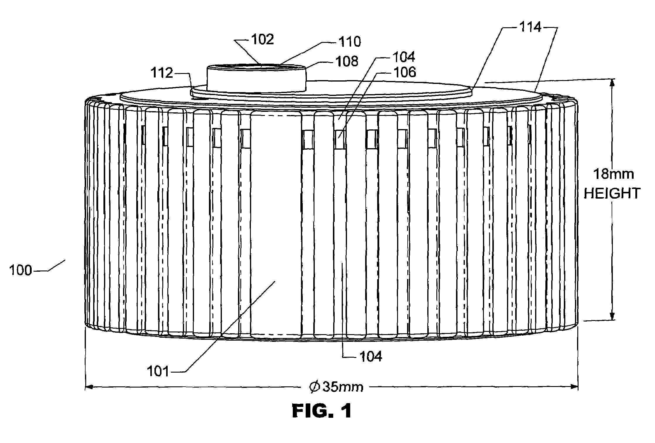
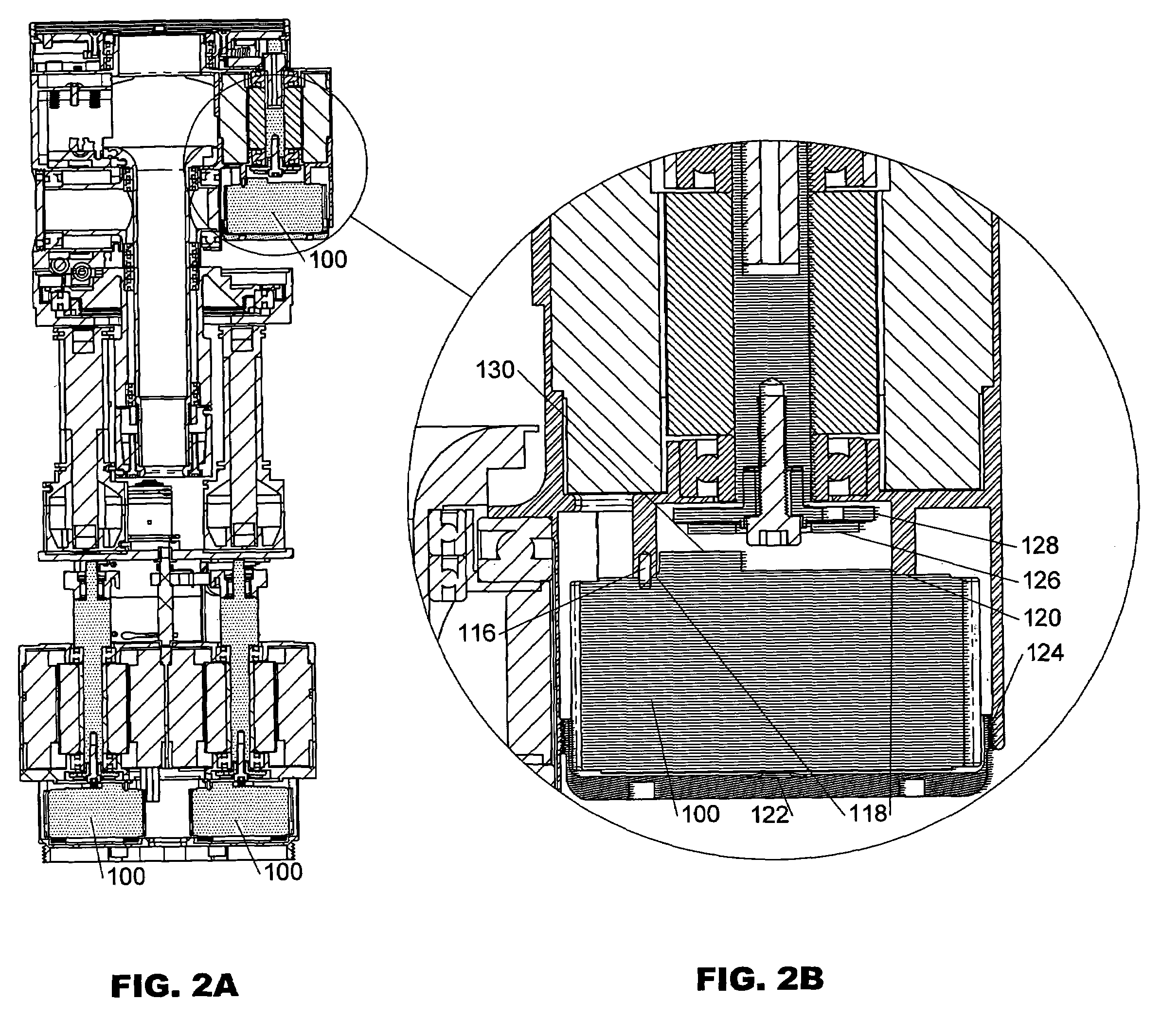
"The present invention is a controller for a motor that is compact, lightweight, and has a relatively isothermal temperature profile. The controller includes a power circuit, a sensor, a signal circuit, and electrical connectors that produce a substantially common potential throughout the controller. The controller is insensitive to noise and can provide high-precision positional determination without increasing the size of the controller. The controller can be used in motor network topologies and can be adapted for power sharing and power generation. The controller includes a thermally conductive, electrically insulating casting that has a low inductance and the external connectors have low inductance. The power circuit includes a PC board, plural power transistors, and a DC to DC transformer. The sensor includes a single current sensor that measures the currents flowing in each of the windings. The controller can be located proximal to the motor and is insensitive to environmental effects. The controller can be used in a network of controllers and their associated motors."

Problems solved by technology

Further, such power and signal circuits, ground, and connectors are ultra-compact to produce substantially the same potential throughout the ground during the operation of the controller.
Such controllers are compact or smaller as compared to prior art controllers, particularly when compared to prior art controllers that handle comparable power.

Method used


Image

  • Ultra-compact, high-performance motor controller and method of using same
  • Ultra-compact, high-performance motor controller and method of using same
  • Ultra-compact, high-performance motor controller and method of using same

Examples


Embodiment Construction

[0046]There are many possible variations of geometry between the stationary and moving parts of electric motors. And the relative motion can be linear, rotary, cylindrical, spherical, or any combination comprising one, two, or many degrees of freedom. This invention is not limited by geometry or type of motions supported.

[0047]There are also many motor constructions, such as servomotors, stepper motors, micro steppers, coreless motors, and induction motors. Some are brushed, some are brushless, some have permanent magnets, and some not. This invention applies to any motor type in which electrical current must be supported through at least one motor winding, whether or not position feedback is required.

[0048]For descriptive clarity, the disclosure of this invention uses generally accepted terminology related to a common permanent-magnet, brushless servomotor: an external set of stationery coils (stator) arranged cylindrically outside a cylindrically-shaped spinning (rotor) shaft carr...


PUM

PropertyMeasurementUnit
transmitted power densityaaaaaaaaaa
lengthaaaaaaaaaa
thicknessaaaaaaaaaa

Abstract

Featured is a controller for a motor that is ultra-compact, with a power density of at least about 20 watts per cubic cm (W / cm3). The controller utilizes a common ground for power circuitry, which energizes the windings of the motor, and the signal circuitry, which controls this energization responsive to signals from one or more sensors. Also, the ground is held at a stable potential without galvanic isolation. The circuits, their components and connectors are sized and located to minimize their inductance and heat is dissipated by conduction to the controller's exterior such as by a thermally conductive and electrically insulating material (e.g., potable epoxy). The controller uses a single current sensor for plural windings and preferably a single heat sensor within the controller. The body of the controller can also function as the sole plug connector.

Description

CROSS-REFERENCE TO RELATED APPLICATIONS [0001]This application is a Continuation-In-Part of U.S. patent application Ser. No. 10 / 672,888, filed Sep. 26, 2003, which claims priority under 35 U.S.C.§119(e) of U.S. Provisional Application No. 60 / 414,044, filed Sep. 26, 2002. This application also claims the benefit of U.S. Provisional Application Ser. No. 60 / 615,490 filed Sep. 30, 2004 and U.S. Provisional Application Ser. No. 60 / 699,564 filed Jul. 15, 2005, the teachings of which are incorporated herein by reference.FIELD OF THE INVENTION [0002]This invention relates in general to controllers for electrical motors and their use topology. More specifically, it relates to an ultra-compact, high performance controller for use on an associated motor that has at least one motor winding that carries an electrical current controlled by the controller, and a network of such motor-controllers.BACKGROUND OF THE INVENTION [0003]Every day modern consumers and workers are aided by dozens of electri...

Claims


Application Information

Patent Timeline
Patent Type & Authority Patents(United States)
IPC IPC(8): H01R13/648
CPCB25J9/1612B25J15/0009B25J15/10C25D11/02H02K11/048H02K11/0005H02K11/0141H02K11/05
Inventor TOWNSEND, WILLIAM T.CROWELL, ADAMPRATT, GILLHAUPTMAN, TRAVELER
Owner BARRETT TECH LLC
Learn More