
Virtual mimo communication system

a communication system and virtual technology, applied in the field of communication, can solve the problems of significant increase in the complexity of mobile terminals, insignificant cost of providing such, and consumers' unwillingness to bear the cost of completing the mimo environment by buying properly equipped mobile terminals

Active Publication Date: 2009-03-24
MALIKIE INNOVATIONS LTD
View PDF27 Cites 85 Cited by
  • Summary
  • Abstract
  • Description
  • Claims
  • Application Information

AI Technical Summary

Benefits of technology

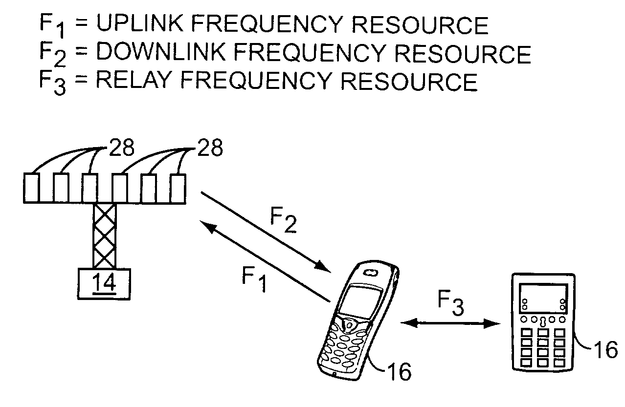
[0004]The present invention provides an effective way to create a virtual MIMO transmission system using mobile terminals that have only one transmit path and antenna. This is accomplished by assigning mobile terminals to a group and assigning certain shared resources and user-specific resources to those mobile terminals in the group. In a synchronized fashion, the mobile terminals will provide uplink transmission in concert, as if they were a single entity having multiple transmission paths and a

Problems solved by technology

Unfortunately, the nature of mobile communications dictates the need for inexpensive mobile terminals, such as mobile telephones, wireless personal digital assistants (PDAs), and the like.
Implementing multiple antennas and transmission paths within mobile terminals significantly increases their complexity, and thus price.
Most base stations are already equipped with multiple antennas and receivers, and given the nature of such infrastructure, the cost of providing such has proven largely insignificant.
Thus, there exists a wireless infrastructure capable of facilitating MIMO-based communication, yet consumers are unwilling to bear the cost of completing the MIMO environment by buying properly equipped mobile terminals.

Method used


Image

  • Virtual mimo communication system
  • Virtual mimo communication system
  • Virtual mimo communication system

Examples


Embodiment Construction

[0022]The embodiments set forth below represent the necessary information to enable those skilled in the art to practice the invention and illustrate the best mode of practicing the invention. Upon reading the following description in light of the accompanying drawing figures, those skilled in the art will understand the concepts of the invention and will recognize applications of these concepts not particularly addressed herein. It should be understood that these concepts and applications fall within the scope of the disclosure and the accompanying claims.

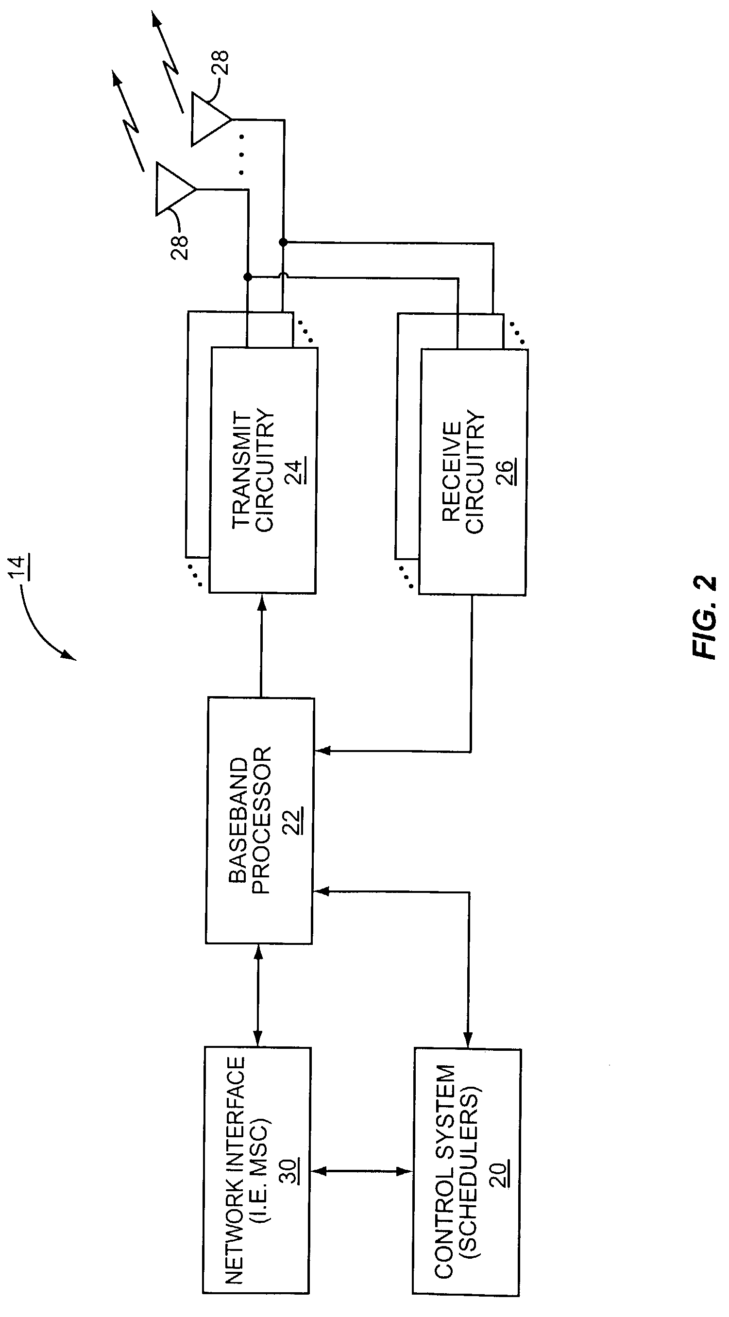
[0023]With reference to FIG. 1, a basic wireless communication environment is illustrated. In general, a base station controller (BSC) 10 controls wireless communications within multiple cells 12, which are served by corresponding base stations (BS) 14. Each base station 14 facilitates communications with mobile terminals 16, which are within the cell 12 associated with the corresponding base station 14. For the present invention,...


PUM


Abstract

The present invention provides an effective way to create a virtual MIMO transmission system using mobile terminals that have only one transmit path and antenna. This is accomplished by assigning mobile terminals to a group and assigning certain shared resources and user-specific resources to those mobile terminals in the group. In a synchronized fashion, the mobile terminals will provide uplink transmission in concert, as if they were a single entity having multiple transmission paths and antennas. Preferably, the shared resources bear on how the data is transmitted, and the user-specific resources relate to pilot signals. The data transmitted may be encoded in any number of ways, and in one embodiment, the mobile terminals may relay their information to each other, such that uplink transmissions can incorporate STTD decoding or other space-time codes. The invention is applicable to virtually any multiple access technology, including OFDM, TDMA, and CDMA, preferably synchronous CDMA.

Description

FIELD OF THE INVENTION[0001]The present invention relates to communications, and more particularly relates to providing a virtual multiple input multiple output communication environment using mobile terminals having only a single transmission path and antenna.BACKGROUND OF THE INVENTION[0002]With the ever-increasing demand for wireless transmission capacity, be it the number of users able to access a system or the speed at which data is transferred, multiple input multiple output (MIMO) architectures have evolved. MIMO architectures incorporate multiple antennas for transmission and multiple receivers for reception. In combination with various coding techniques, the spatial diversity provided by MIMO systems provides for significant increases in the number of users that can access a system at any given time, as well as the amount of data that can be transmitted over a given period of time. Unfortunately, the nature of mobile communications dictates the need for inexpensive mobile t...

Claims


Application Information

Patent Timeline
IPC IPC(8): H04Q11/00H04B7/06H04B7/08H04J11/00H04J13/16H04L1/00H04L1/06H04L25/02
CPCH04B7/026H04B7/0669H04B7/0891H04J13/16H04L1/0618H04L5/0035H04L5/0048H04L5/0094H04L25/0226H04L1/0026H04L5/0026
Inventor TONG, WENMA, JIANGLEIZHU, PEIYINGJIA, MINGYU, DONG-SHENG
Owner MALIKIE INNOVATIONS LTD
Learn More