Exposure apparatus and device manufacturing method

a manufacturing method and technology of an exposure apparatus, applied in the field of exposure apparatus and a device manufacturing method, can solve the problems of not always maintaining the control over the polarization state of the exposure light at the pupil position in the illumination optical system, prior art cannot handle changes in the polarization state, and cannot maintain the desired polarization state. , to achieve the effect of improving resolution and without lowering throughpu

Inactive Publication Date: 2009-03-24
CANON KK
View PDF9 Cites 47 Cited by
  • Summary
  • Abstract
  • Description
  • Claims
  • Application Information

AI Technical Summary

Benefits of technology

[0008]The present invention is directed to an exposure apparatus that precisely controls a polarization state of exposure light without lowering a throughput, and can improve the resolution.

Problems solved by technology

In addition, control over a polarization state of the exposure light at a pupil position in the illumination optical system is not always maintained on the image plane due to the influence of the optical system after the pupil position in the illumination optical system and the projection optical system.
Therefore, the prior art cannot handle changes of the polarization state in each area of the polarization illumination, or cannot maintain the desired polarization state.

Method used


Image

  • Exposure apparatus and device manufacturing method
  • Exposure apparatus and device manufacturing method
  • Exposure apparatus and device manufacturing method

Examples


Embodiment Construction

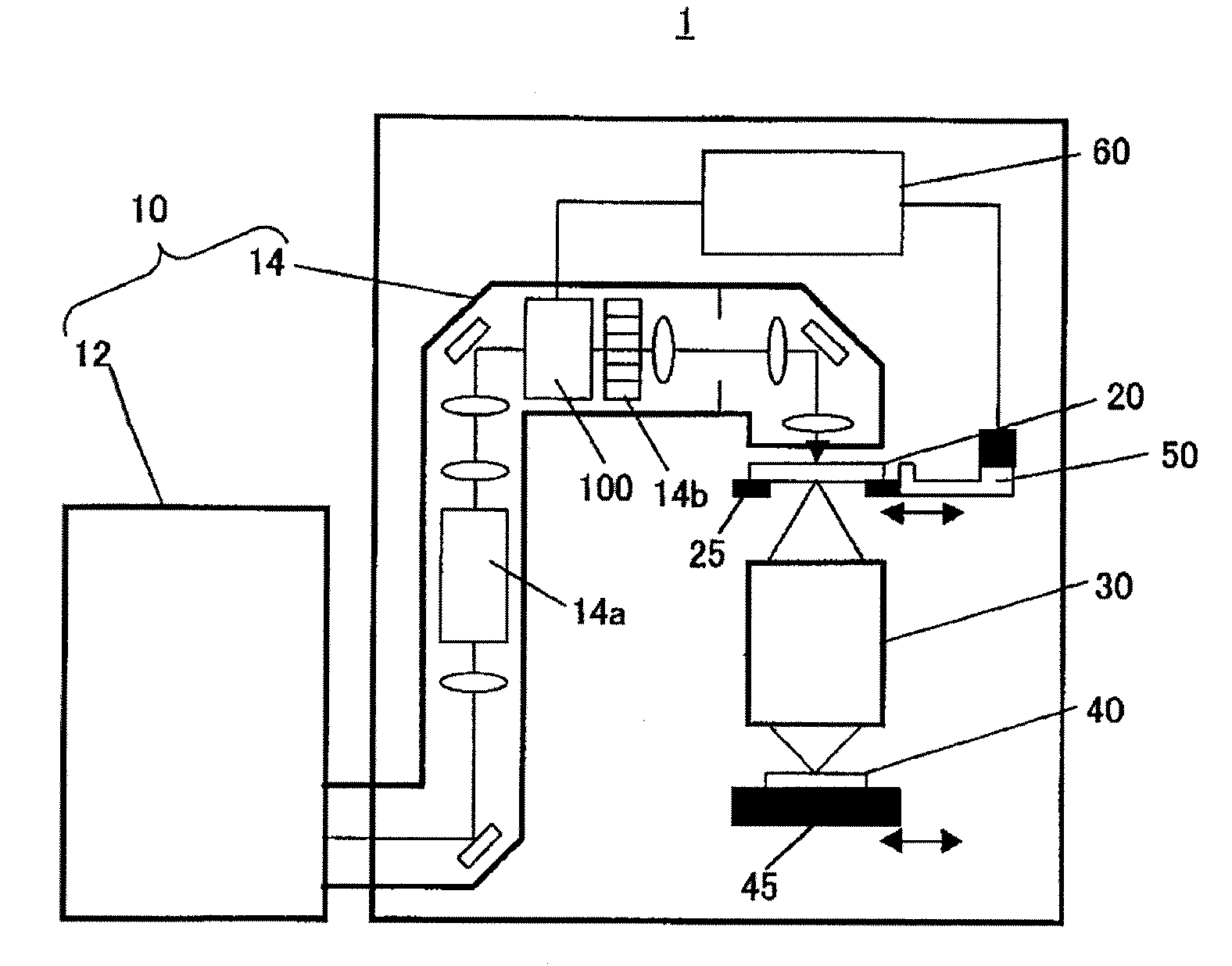
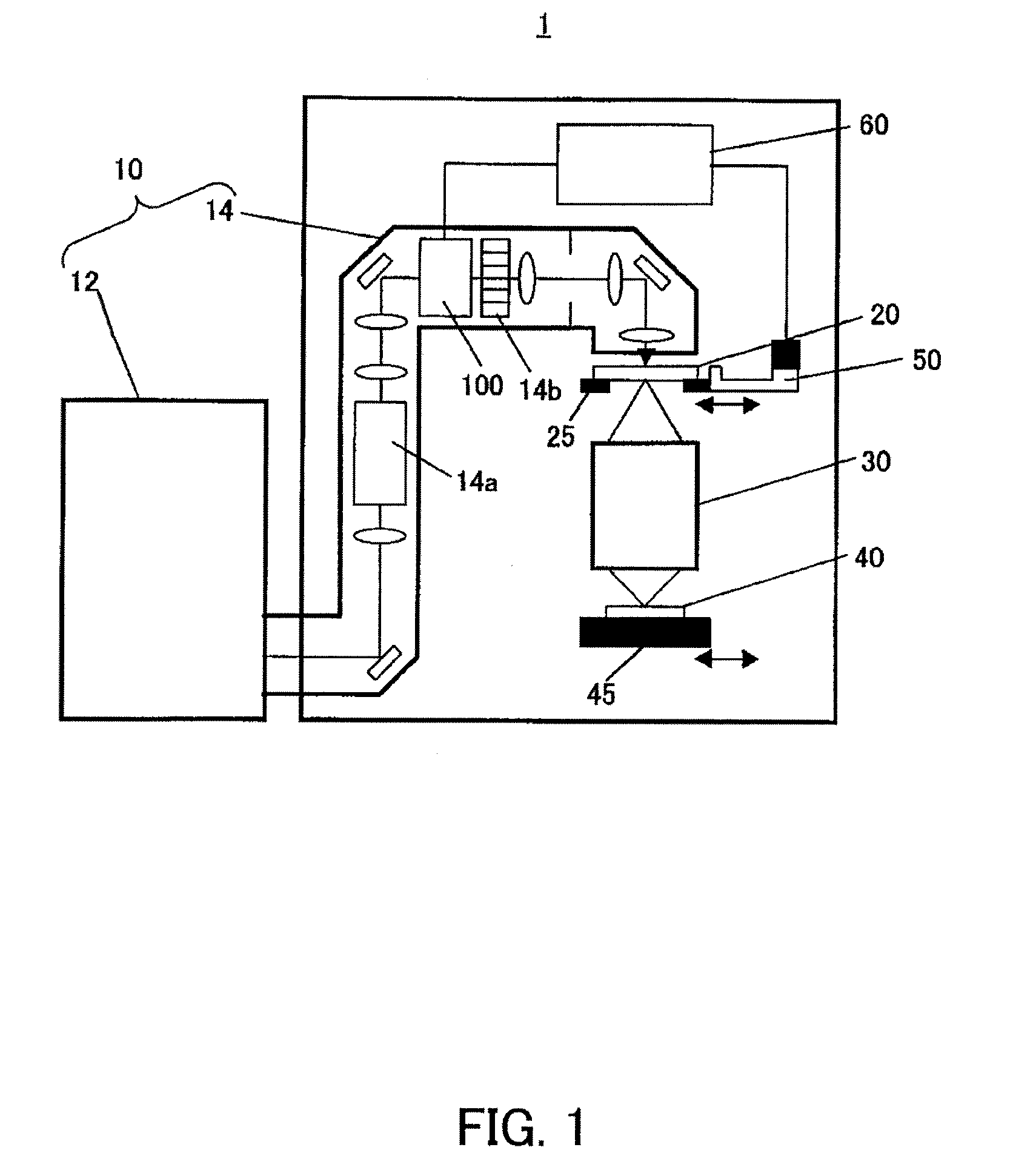
[0030]Referring now to the accompanying drawings, a description will be given of an exposure apparatus according to one aspect of the present invention. In each figure, the same reference numeral designates the same element, and a duplicate description thereof will be omitted. Here, FIG. 1 is a schematic sectional view showing a structure of an exposure apparatus 1 according to the present invention.

[0031]The exposure apparatus 1 is a projection optical system that irradiates the light emitted from the light source 12 onto a wafer 40 via plural optical systems, and exposes a circuit pattern of a reticle 20 onto the wafer 40. The exposure apparatus 1 uses a step-and-scan exposure manner, but may use a step-and-repeat manner. The following embodiment discusses a step-and-scan exposure apparatus.

[0032]The exposure apparatus 1 includes, as shown in FIG. 1, an illumination apparatus 10, a reticle stage 25 mounted with a reticle 20, a projection optical system 30, a wafer stage 45 mounted...


PUM


Abstract

An exposure apparatus includes an illumination optical system configured to illuminate a reticle, a projection optical system configured to project a pattern of the reticle onto a substrate, a polarization adjuster configured to independently adjust each polarization state of plural areas in an effective light source distribution used to illuminate the reticle, a polarization measurement unit configured to measure a polarization state of light that has passed the polarization adjuster, and a controller configured to independently control each polarization state of the plural areas via the polarization adjuster based on a measurement result of the polarization measurement unit.

Description

BACKGROUND OF THE INVENTION[0001]The present invention relates to an exposure apparatus and a device manufacturing method.[0002]A conventional projection exposure apparatus projects a circuit pattern of a reticle (mask) onto a wafer via a projection optical system in manufacturing semiconductor devices using the photolithography technology.[0003]Along with a demand for fine processing to a semiconductor device, a recently proposed exposure apparatus can expose a pattern as small as half an exposure wavelength. A shorter wavelength of the exposure light and a higher numerical aperture (“NA”) of the projection optical system are used for such a high resolution. An increase of a NA of the projection optical system means an increase of an angle between a perpendicular from an image plane and a traveling direction of the incident light, and is referred to as high NA imaging.[0004]A polarization of the exposure light is crucial to high NA imaging. For example, in exposing a so-called line...

Claims


Application Information

Patent Timeline
Patent Type & Authority Patents(United States)
IPC IPC(8): G03B27/72
CPCG03F7/70108G03F7/70566G03F7/70191
Inventor TAKEUCHI, SEIJIYAMAZOE, KENJIOHSAKI, YUMIKOYOSHII, MINORU
Owner CANON KK
Why Eureka
Try Eureka