
Honeycomb type solid electrolytic fuel cell

a fuel cell and honeycomb technology, applied in the direction of cell components, final product manufacturing, sustainable manufacturing/processing, etc., can solve the problems of not always being the optimum energy-saving system, requiring a huge capital investment for social infrastructure, and it is difficult to assert the advantage of using them in comparison with existent heat engines, hybrid cars,

Inactive Publication Date: 2009-03-24
THINKTANK PHOENIX
View PDF3 Cites 14 Cited by
  • Summary
  • Abstract
  • Description
  • Claims
  • Application Information

AI Technical Summary

Problems solved by technology

Among these fuel cells of second generation, PEFCs which use a fluorine or hydrocarbon type polymer electrolyte film as the electrolyte, have many disadvantages that the fuel used is limited to pure hydrogen (H2); temperature control of very narrow range (from 65° C. to 85° C.) is required; a delicate control is necessary to determine the water (H2O) content in the electrolyte film; a large quantity of expensive platinum catalyst has to be used; the durability is only about from 2,000 to 3,000 hours, and freezing should be avoided, consequently, they can not be used in a cold district because there is a danger of freezing.
Further, since the fuel used is limited to pure hydrogen, it is necessary to restructure entirely the existent social infrastructure (e.g., gas, LPG, petroleum etc.) to be adapted to a hydrogen system, which requires a huge capital investment for social infrastructure.
In addition, there are disadvantages that since the working temperature is low and therefor, the exhaust temperature is low, it is difficult to recover effectively exhaust heat in, for example, a co-generation system, and if the demand of heat is higher than the demand of electric power, a combustion aid using an expensive hydrogen fuel is needed, and accordingly, they can not always be the optimum energy-saving system from the viewpoint of heat balance.
Further, since PEFC requires expensive pure hydrogen fuel, it would be difficult to assert the advantage in using them in comparison with existent heat engines, hybrid cars etc. when efficiency including hydrogen production cost is considered.
Further, it was unable to follow a rapid load change.
Accordingly, it had the disadvantages that a thermal stress generated in each part of the structural body could not sufficiently be reduced, and the starting time could not sufficiently be shortened.
Accordingly, it took much time for warming-up from the starting of the apparatus to a full power state, thus, there was a drawback of being inconvenient.
Accordingly, the exhaust contains large quantities of unreacted fuel and unreacted oxygen, and therefor, sufficient power generation efficiency could not be expected.
However, the disclosed fuel cells belong a honeycomb type fuel cell in which fuel pole cells and air pole cells adjacent to each other are arranged alternately in a form of so-called checker board design, and no means for removing heat generated in its honeycomb cells is provided.
Accordingly, heat built up in the honeycomb to elevate the temperature in the honeycomb, and on the other hand, the outer peripheral portion of the honeycomb was cooled by heat radiation and cooldown, with the result that a large temperature difference was resulted between the central portion and the outer peripheral portion of the honeycomb, whereby the breakage of the honeycomb was caused due to a thermal stress by the temperature difference.
Further, in these fuel cells, it was necessary to elevate gradually the temperature with a sufficient warming-up time after the starting of the apparatus to a normal operation, hence, there was a drawback of being inconvenient.
Further, since the concentration of unreacted fuel gas and the concentration of unreacted oxygen contained in the exhaust gas also were high, whereby the power generation efficiency could not sufficiently be increased.
Further, the output density per unit surface area could not be increased.

Method used


Image

  • Honeycomb type solid electrolytic fuel cell
  • Honeycomb type solid electrolytic fuel cell
  • Honeycomb type solid electrolytic fuel cell

Examples


example

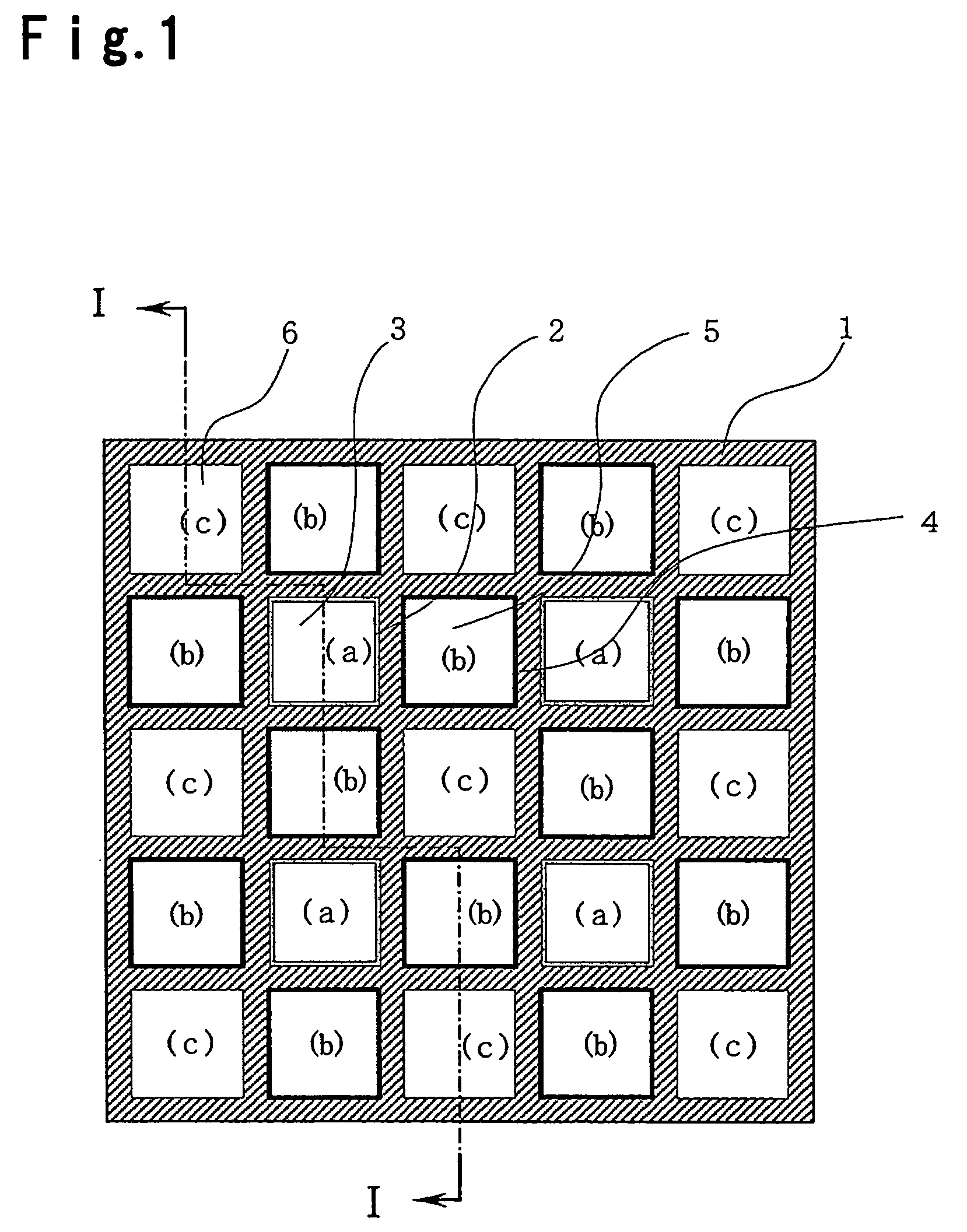
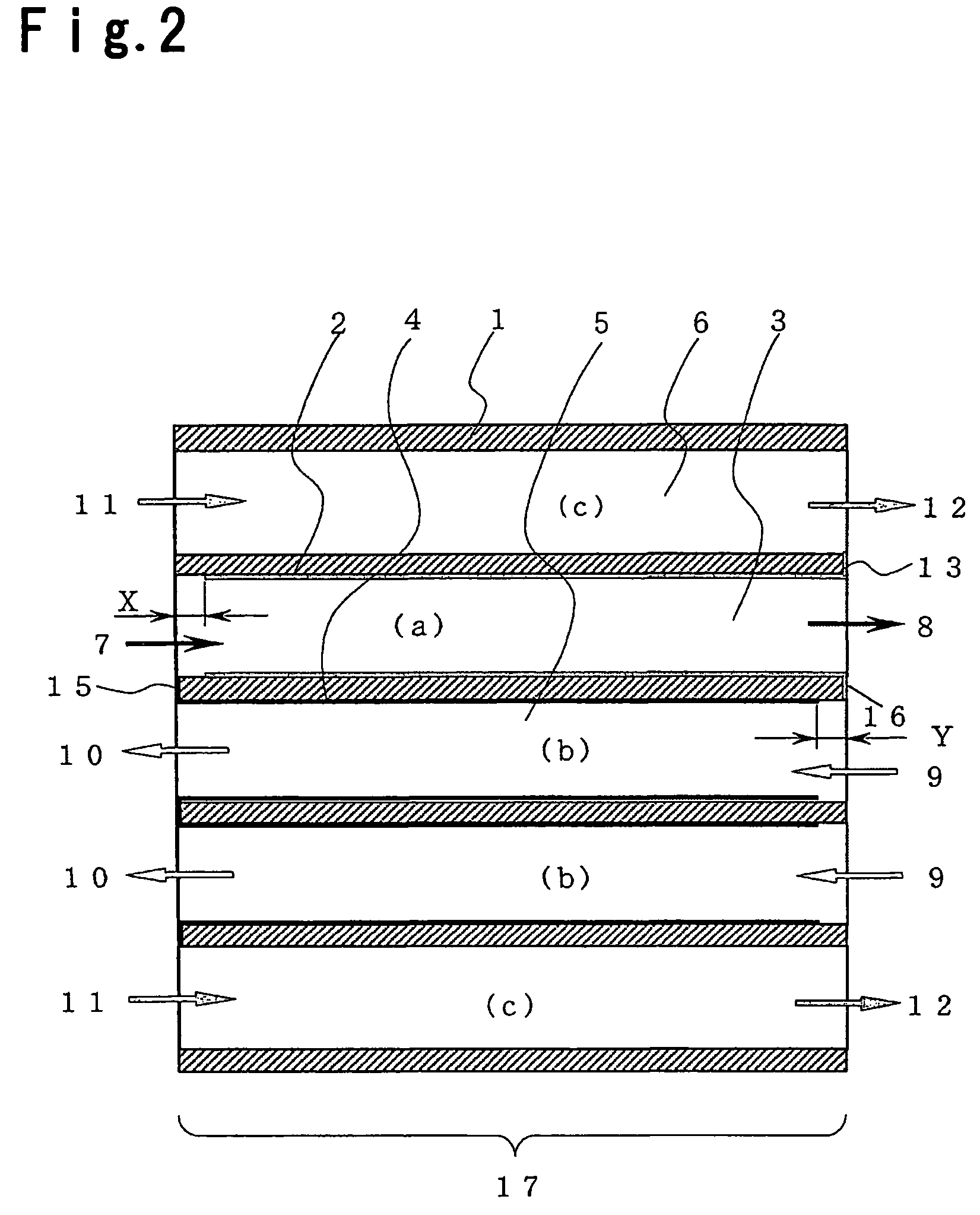
[0059]An example of the solid-oxide fuel cell of the present invention will be described in more detail with reference to FIG. 4. The stacked type honeycomb fuel cell 18 shown in FIGS. 1 to 3 has the honeycomb structural body comprising cells of 5 rows and 5 columns. On the other hand, FIG. 4 shows the structure comprising cells of 7 rows and 7 columns, which is likely to be used practically. The structure and function in this embodiment, except for this point are substantially the same as those described with reference to FIGS. 1 to 3.

[0060]FIG. 4 shows a fuel cell depicted in a separate state to be two stages in vertical direction. However, the arrangement of two stages is made for descriptive purpose of the figure and in fact, all structural elements are connected linearly on a single center line.

[0061]The stacked type honeycomb fuel cell 18 has an air inlet / outlet-side end surface 25 to which a honeycomb-shaped air inlet / outlet-side collecting / insulating unit 26 in which only fu...


PUM

PropertyMeasurementUnit
temperatureaaaaaaaaaa
electricaaaaaaaaaa
shapeaaaaaaaaaa

Abstract

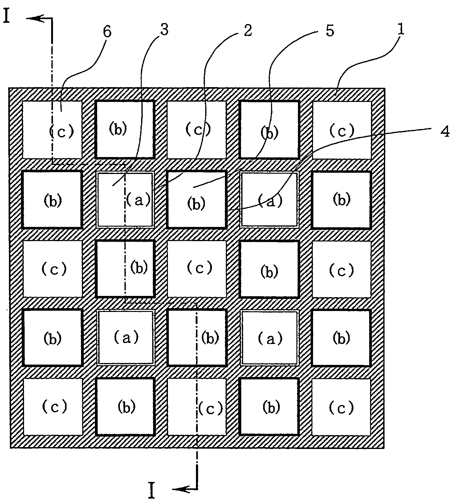
A SOFC type fuel cell being small in size and large in output while providing good efficiency and being excellent in starting characteristics and load variation characteristics, is presented. A honeycomb type solid-oxide fuel cell is formed of a honeycomb structural body having square cell in cross section, wherein cells adjacent to wall surfaces constituting a fuel pole cell (a) function as air pole cells (b) and cells adjacent to the corners of wall surfaces of the fuel pole cell and adjacent to wall surfaces constituting air pole cell function as cooling air cells (c), whereby fuel pole cells, air pole cells and cooling air cells are arranged in longitudinal and lateral rows so that cells of the same type appear in every other location.

Description

TECHNICAL FIELD[0001]The present invention relates to a honeycomb type solid-oxide fuel cell using any of a solid-oxide material, a fuel pole cell or an air pole cell as its structural body.BACKGROUND ART[0002]Fuel cells have been in the transition from the fuel cells of first generation which use a liquid substrate such as a phosphoric acid aqueous solution or fused carbonate for the fuel cells of second generation such as polymer electrolyte type fuel cells (hereinbelow, referred to as PEFC) or solid-oxide electrolyte type fuel cells (hereinbelow, referred to as SOFC). Among these fuel cells of second generation, PEFCs which use a fluorine or hydrocarbon type polymer electrolyte film as the electrolyte, have many disadvantages that the fuel used is limited to pure hydrogen (H2); temperature control of very narrow range (from 65° C. to 85° C.) is required; a delicate control is necessary to determine the water (H2O) content in the electrolyte film; a large quantity of expensive pla...

Claims


Application Information

Patent Timeline
Patent Type & Authority Patents(United States)
IPC IPC(8): H01M8/12H01M8/04H01M8/06H01M8/24
CPCH01M8/04007H01M8/04014H01M8/04097H01M8/0625H01M8/1206H01M8/1246H01M8/2435H01M8/04022Y02E60/521Y02E60/525H01M8/1231Y02E60/50Y02P70/50H01M8/2484
Inventor TORIYAMA, AKIRA
Owner THINKTANK PHOENIX
Learn More