
Drying jig assembling apparatus, drying jig disassembling apparatus, drying jig circulating apparatus, drying method of ceramic molded body, and method for manufacturing honeycomb structure

a technology of drying jigs and circulating apparatuses, which is applied in the direction of manufacturing tools, lighting and heating apparatus, and drying machines with progressive movements. it can solve the problems of contamination of the environment and the human body, and serious problems

Inactive Publication Date: 2008-05-08
IBIDEN CO LTD
View PDF99 Cites 108 Cited by
  • Summary
  • Abstract
  • Description
  • Claims
  • Application Information

AI Technical Summary

Problems solved by technology

In recent years, particulates such as soot contained in exhaust gases that are discharged from internal combustion engines of vehicles such as buses and trucks, and construction machines and the like, have raised serious problems as contaminants harmful to the environment and the human body.

Method used


Image

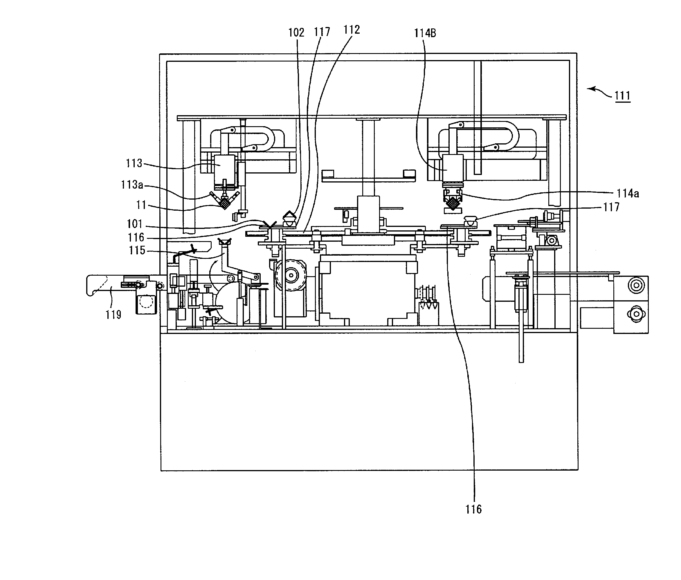
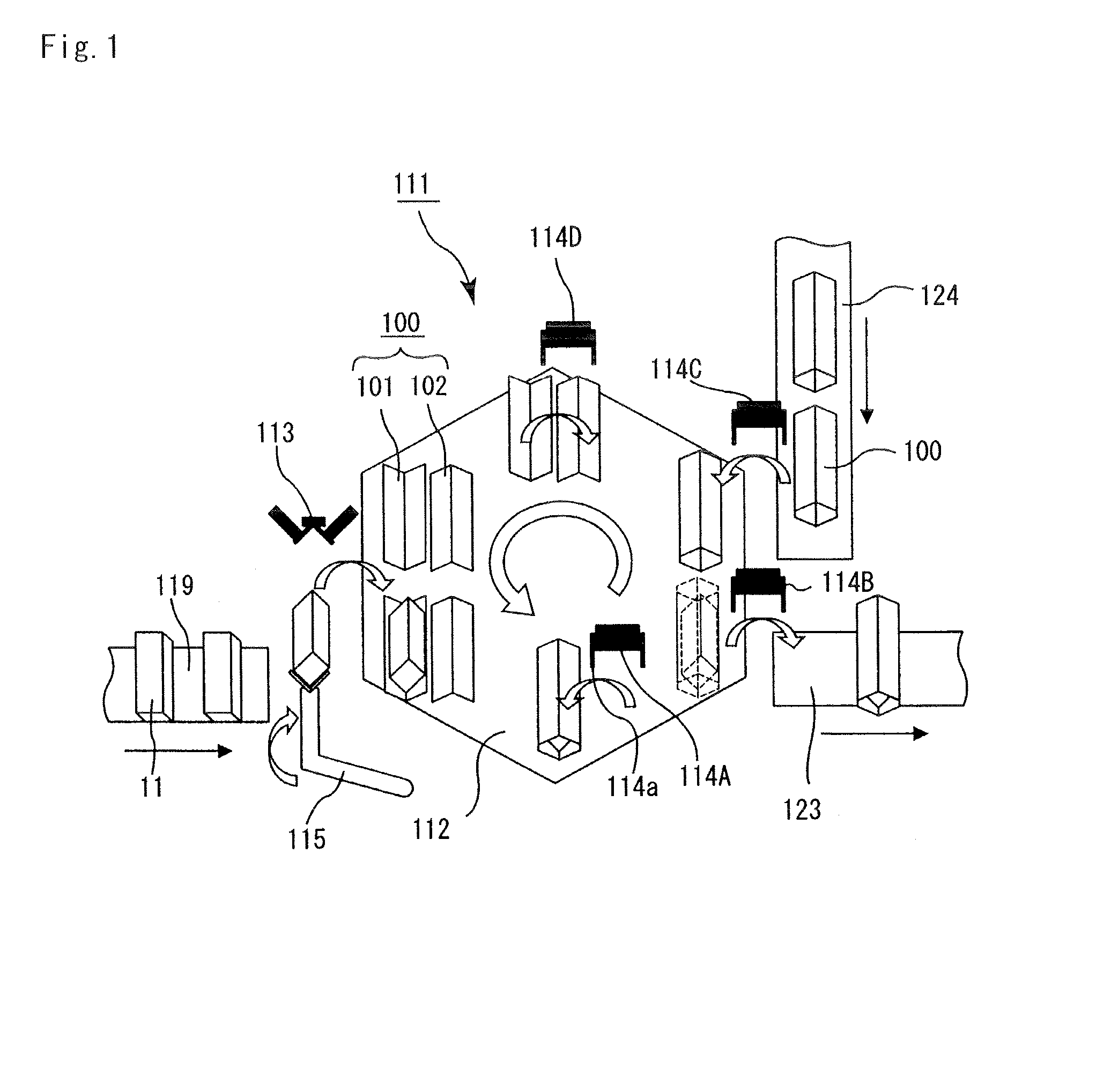
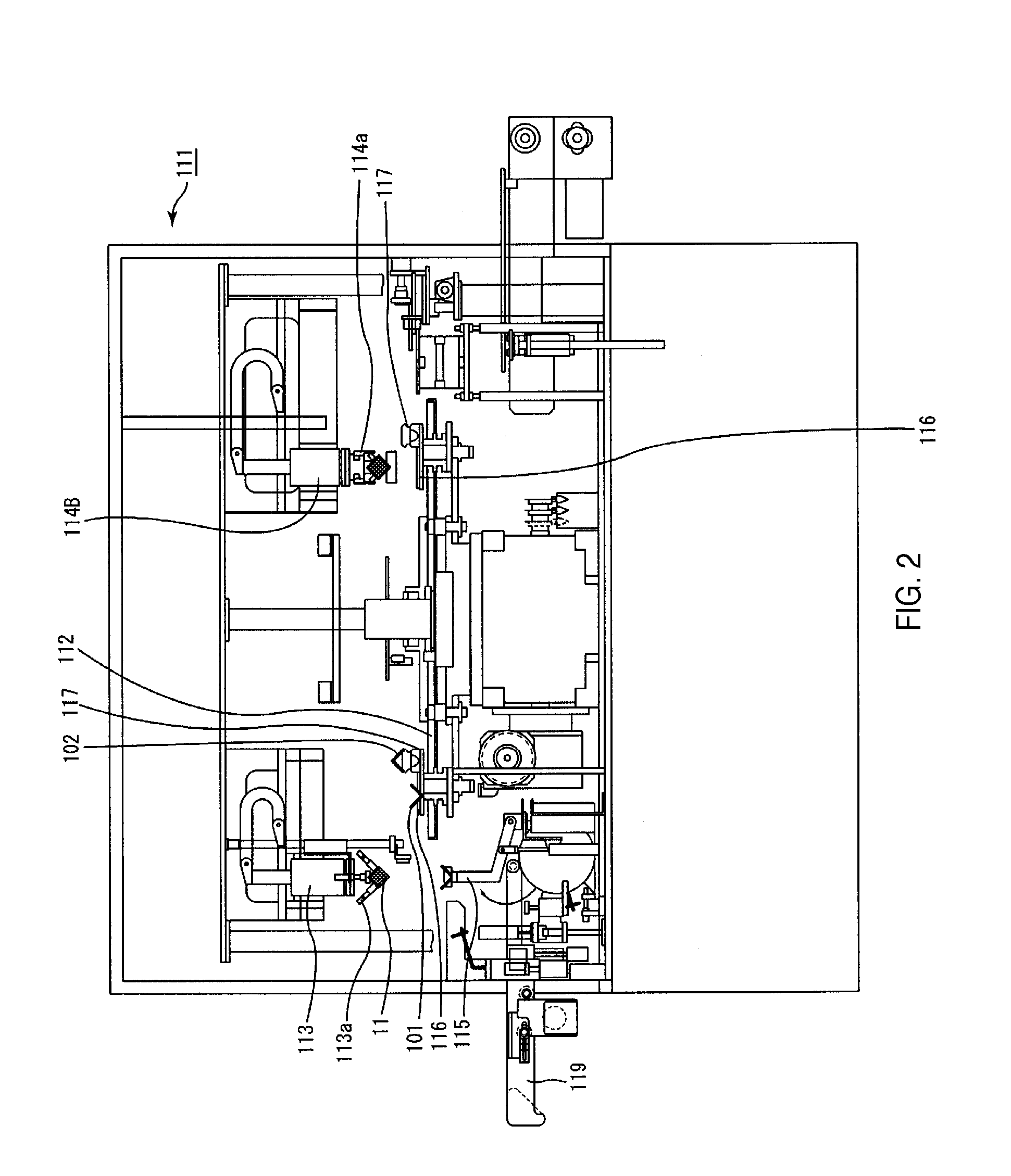
  • Drying jig assembling apparatus, drying jig disassembling apparatus, drying jig circulating apparatus, drying method of ceramic molded body, and method for manufacturing honeycomb structure
  • Drying jig assembling apparatus, drying jig disassembling apparatus, drying jig circulating apparatus, drying method of ceramic molded body, and method for manufacturing honeycomb structure
  • Drying jig assembling apparatus, drying jig disassembling apparatus, drying jig circulating apparatus, drying method of ceramic molded body, and method for manufacturing honeycomb structure

Examples


example 1

[0294] Powder of α-type silicon carbide having an average particle diameter of 10 μm (250 kg), powder of α-type silicon carbide having an average particle diameter of 0.5 μm (100 kg) and an organic binder (methylcellulose) (20 kg) were mixed to prepare mixed powder.

[0295] Next, separately, a lubricant (UNILUB, manufactured by NOF Corp.) (12 kg), a plasticizer (glycerin) (5 kg) and water (65 kg) were mixed to prepare a liquid mixture, and this liquid mixture and the mixed powder were mixed by using a wet mixer so that a wet mixture was prepared.

[0296] Here, the moisture content of the wet mixture prepared was 14% by weight.

[0297] Next, this wet mixture was transported to an extrusion molding machine by using a transporting device, and charged into a material charging port of the extrusion molding machine.

[0298] The moisture content of the wet mixture immediately before the charging into the extrusion molding machine was 13.5% by weight.

[0299] The wet mixture was then extrusion-m...


PUM

PropertyMeasurementUnit
angleaaaaaaaaaa
angleaaaaaaaaaa
angleaaaaaaaaaa

Abstract

A drying jig circulating apparatus includes a drying jig assembling apparatus for assembling a drying jig on a movable table, a drying apparatus for drying a ceramic molded body held by the drying jig, and a drying jig disassembling apparatus for disassembling the drying jig on a movable table, and a drying jig circulating conveyor for transporting the drying jig from the disassembling apparatus to the assembling apparatus. The drying jig is configured by two or more separate jigs with a fixing member that integrates the separate jigs, or formed by one openable jig with a fixing member for maintaining a closed state. The drying jig assembling apparatus further includes a molded body mounting mechanism, a ceramic molded body holding mechanism, and a jig delivering mechanism. The drying jig disassembling apparatus further includes a jig receiving mechanism, a jig releasing mechanism, and a molded body taking-out mechanism.

Description

CROSS-REFERENCE TO RELATED APPLICATIONS [0001] This application claims priority under 35 U.S.C. §120 as a continuation application of PCT / JP2006 / 302862 filed on Feb. 17, 2006. The contents of this application are incorporated herein by reference in their entirety.BACKGROUND OF THE INVENTION [0002] 1. Field of the Invention [0003] The present invention relates to a drying jig assembling apparatus, a drying jig disassembling apparatus, a drying jig circulating apparatus, a drying method of a ceramic molded body, and a method for manufacturing a honeycomb structure. [0004] 2. Discussion of the Background [0005] In recent years, particulates such as soot contained in exhaust gases that are discharged from internal combustion engines of vehicles such as buses and trucks, and construction machines and the like, have raised serious problems as contaminants harmful to the environment and the human body. [0006] Various honeycomb filters using honeycomb structures made from porous ceramic mat...

Claims


Application Information

Patent Timeline
Patent Type & Authority Applications(United States)
IPC IPC(8): C04B33/30
CPCB28B11/243Y10T29/53961B28B17/00C04B35/565C04B35/6263C04B35/6316C04B35/806C04B37/005C04B2235/3418C04B2235/3826C04B2235/5228C04B2235/526C04B2235/5264C04B2235/5436C04B2235/5445C04B2235/5472C04B2235/606C04B2237/083C04B2237/365F26B15/14F26B25/003F26B2210/02Y10T29/53974B28B11/248C04B35/80
Inventor KASAI, KENICHIRONARUSE, KAZUYA
Owner IBIDEN CO LTD
Learn More