
DC offset correction using multiple configurable feedback loops

a feedback loop and offset correction technology, applied in the field of dc offset correction, can solve problems such as dc offset and dc offset error associated with downconversion in communication receivers

Active Publication Date: 2009-03-17
QUALCOMM TECH INT
View PDF29 Cites 10 Cited by
  • Summary
  • Abstract
  • Description
  • Claims
  • Application Information

AI Technical Summary

Benefits of technology

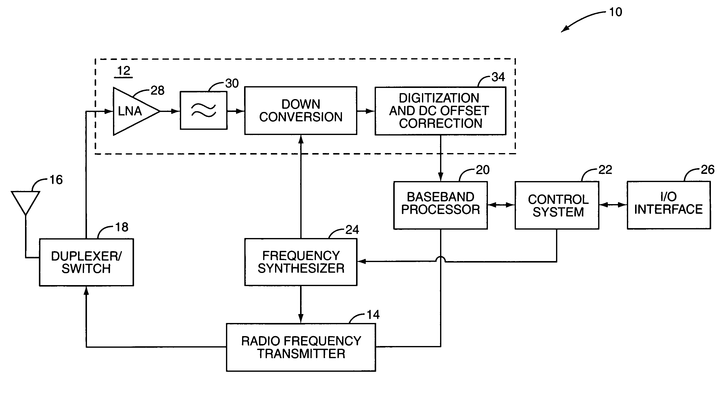
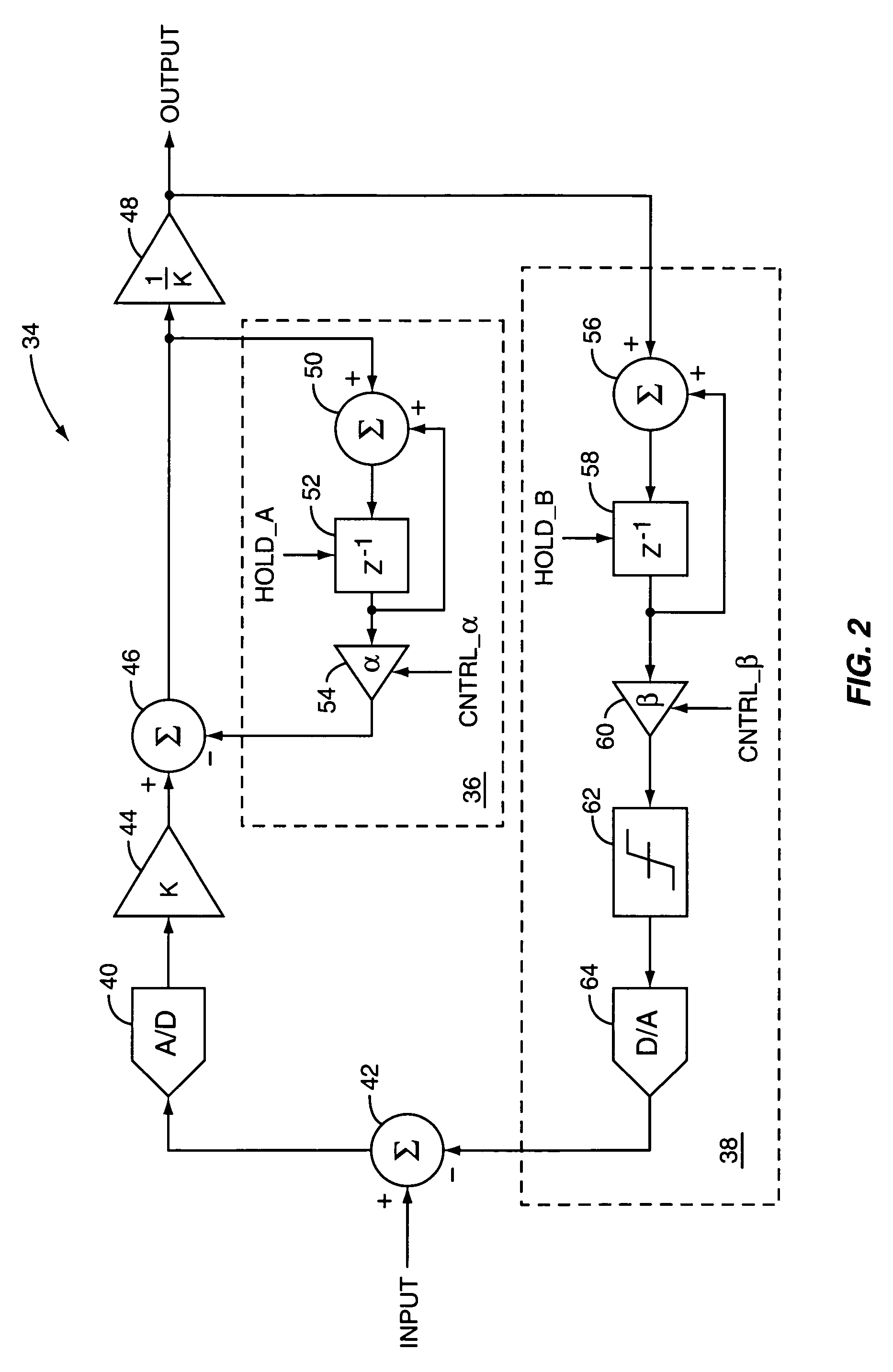
[0003]The present invention provides a DC offset correction system for a wireless communication device that removes a DC offset from a baseband receive signal during “training time” when the baseband receive signal should ideally have no DC content. In general, the DC offset correction system includes multiple configurable feedback loops that operate to remove, or cancel, the DC offset from the baseband receive signal. One or more of the multiple configurable feedback loops is activated, or set to a tracking mode of operation, for a period of time during reception when it is known that the received signal should ideally contain no DC content. This training time varies depending on the particular communication standard being used by the wireless communication device. For example, one or more of the multiple configurable feedback loops

Problems solved by technology

A common problem in wireless communication receivers is DC offset.
When downconverting the RF signals, the LO signal leaks to the inputs of mixers used to downconvert the RF signals, thereby creating a DC offset error associated with downconversion.

Method used


Image

  • DC offset correction using multiple configurable feedback loops
  • DC offset correction using multiple configurable feedback loops
  • DC offset correction using multiple configurable feedback loops

Examples


Embodiment Construction

[0009]The embodiments set forth below represent the necessary information to enable those skilled in the art to practice the invention and illustrate the best mode of practicing the invention. Upon reading the following description in light of the accompanying drawing figures, those skilled in the art will understand the concepts of the invention and will recognize applications of these concepts not particularly addressed herein. It should be understood that these concepts and applications fall within the scope of the disclosure and the accompanying claims.

[0010]While the present invention is particularly well-suited for use in a mobile terminal, and particularly a mobile terminal that operates according to the IEEE 802.11 standard, it should be appreciated that the present invention may be used in any wireless receiver operating according to a standard such as, but not limited to, the Global System for Mobile Communications (GSM) standard, the Time Division Multiple Access (TDMA) s...


PUM


Abstract

The present invention provides a DC offset correction system for a wireless communication device that removes a DC offset from a baseband receive signal during “training time” when the baseband receive signal should ideally have no DC content. In general, the DC offset correction system includes multiple configurable feedback loops that operate to remove or cancel the DC offset from the baseband receive signal. One or more of the multiple configurable feedback loops is activated for a period of time during operation when it is known that the received signal should ideally contain no DC content. This training time varies depending on the particular communication standard being used by the wireless communication device. For example, the training time may be during reception of the preamble and header of an IEEE 802.11 packet.

Description

FIELD OF THE INVENTION[0001]The present invention relates to a wireless communication system, and more particularly to DC offset correction using multiple configurable feedback loops and performed during “training time” having no DC content.BACKGROUND OF THE INVENTION[0002]A common problem in wireless communication receivers is DC offset. This is especially a concern in Direct Conversion Receivers (DCRs) where received radio frequency (RF) signals are converted directly to baseband using a local oscillator (LO) signal having a frequency equal to the frequency of the received RF signals. When downconverting the RF signals, the LO signal leaks to the inputs of mixers used to downconvert the RF signals, thereby creating a DC offset error associated with downconversion. Accordingly, there remains a need for a DC offset correction system that corrects DC offset errors caused by LO leakage as well as any other DC offsets in a receiver for a wireless communication system.SUMMARY OF THE INV...

Claims


Application Information

Patent Timeline
IPC IPC(8): H04B1/10H04B7/00
CPCH04B1/30H04L25/061
Inventor SHAN, PEIJUN
Owner QUALCOMM TECH INT
Learn More