
Polarisation fluorometer

a fluorometer and polarisation technology, applied in the field of polarisation fluorometers, can solve the problems of reducing the efficiency of excitation light access to the emission detector, and polarisation measurements as a function of excitation wavelength and emission wavelength (p()) are difficult to carry ou

Active Publication Date: 2009-03-17
THERMO ELECTRONICS INC THERMO ELECTRONICS INC
View PDF7 Cites 4 Cited by
  • Summary
  • Abstract
  • Description
  • Claims
  • Application Information

AI Technical Summary

Benefits of technology

"The invention is a polarization fluorometer that uses a stationary polarization filter in the emission channel and a replaceable polarization filter in the excitation channel. The device can be calibrated by measuring the excitation intensity on two polarization planes without needing a sample. The device also includes a reference detector for accurate measurements. The technical effect of this invention is a more efficient and accurate method for measuring fluorescence spectra."

Problems solved by technology

This reduces efficiently the access of excitation light to the emission detector.
Nevertheless, this manner of measuring involves numerous problems:1. A complex design; a dual polarisation filter, requiring the filter to be positioned at an angle of exactly 90 degrees.2. The measurement consists of four measurements and is hence slow.
This is awkward if the measurement is conducted on a sample whose polarisation is unknown.
This method also involves problems:1. Maintaining the solution for any incidental measurements; fluoresceine, for instance, is apt only for applications using fluoresceine as a fluorophore.2. Spectral polarisation measurements as a function of the excitation wavelength and the emission wavelength (P(λ)) are difficult to carry out.

Method used


Image

  • Polarisation fluorometer
  • Polarisation fluorometer
  • Polarisation fluorometer

Examples


examples

[0084]Examples of different embodiments of the invention are given below. The examples use a horizontal polarisation plane in the emission channel, however, similar arrangements can naturally be carried out e.g. by means of vertical emission polarisation. The relative mutual position of the polarisation filters of the excitation channel and the emission channel is essential in this case.

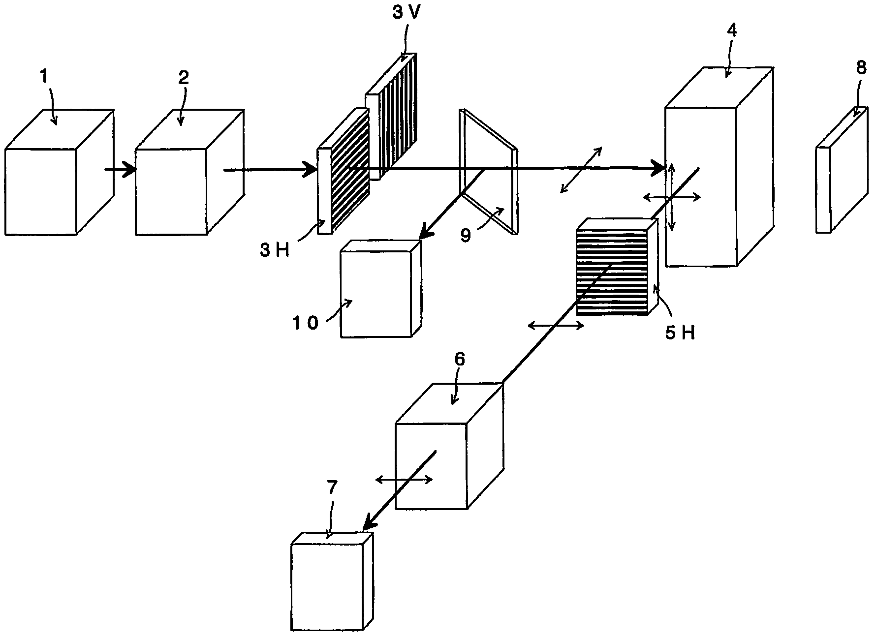
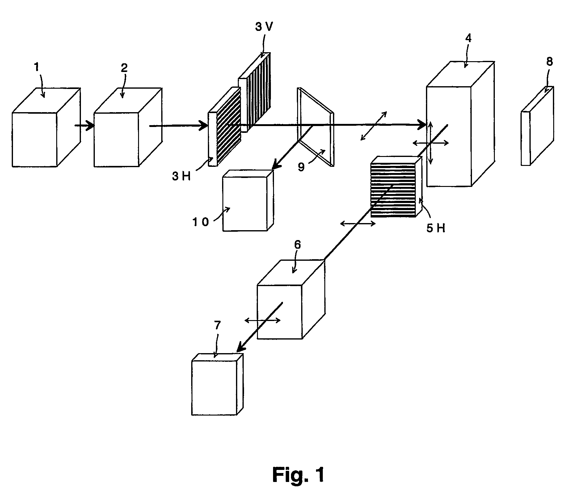
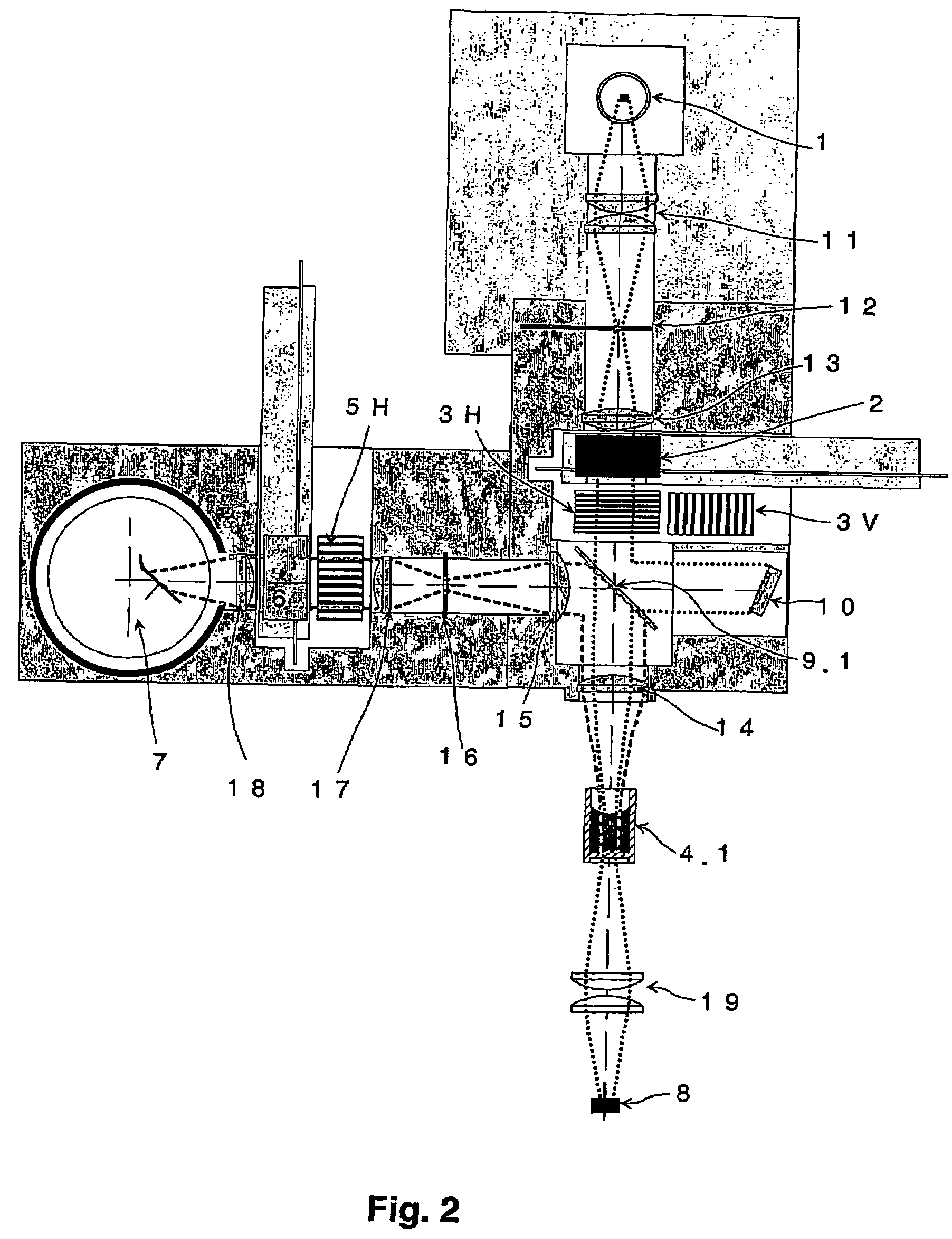
[0085]In the fluorometric measurement illustrated in FIG. 1, the excitation light from light source 1 is conducted to excitation monochromator 2 and through the excitation polarisation filter 3H or 3v to the sample vessel 4. The emission light generated in the sample vessel is conducted in a direction perpendicular to the excitation light through the emission polarisation filter 5H and the emission monochromator 6. The emission light thus generated is conducted to the detector 7. The emission polarisation filter is thus stationary, while the excitation filter is replaceable.

[0086]For determination of...


PUM

PropertyMeasurementUnit
angleaaaaaaaaaa
timeaaaaaaaaaa
mutual angleaaaaaaaaaa

Abstract

A polarization fluorometer and a method for calibrating such a fluorometer. The fluorometer includes an excitation channel with an excitation polarizer for generating light polarized in a first plane or in a second plane to be conducted as a excitation light to a sample, an emission channel for conducting emission light from the sample, in which emission channel there is an emission polarization filter, an excitation detector, to which light polarized by the excitation polarizer can be conducted from the excitation channel, and a reference detector, to which light polarized by the excitation polarizer can be conducted from the excitation channel before being conducted to the sample or to the excitation detector. The reference detector can be calibrated by the excitation detector so that correction measurements can be carried out in real time during sample measurement. The fluorometer can be used especially for fluorescence spectra measurements.

Description

FIELD OF TECHNOLOGY[0001]The invention relates to a polarisation fluorometer and is directed to the calibration of the fluorometer. The invention is applicable to analysers for examining the chemical properties of samples by means of polarisation fluorometry. Such studies are conducted in biotechnology and clinical chemistry laboratories in particular.TECHNOLOGICAL BACKGROUND[0002]In fluorometry, excitation light on a given wavelength is directed to a sample. Illumination generates fluorescence in any fluorophore present in the sample, thus generating emission light having a longer wavelength.[0003]If the excitation light is polarised, it will act in the fluorophore molecules settled correctly relative to the excitation light polarisation, and the emission light is polarised as well. The emission polarisation angle is specific for the fluorophore and dependent on the wavelength.[0004]An emission may be depolarised for different reasons. Depolarisation is caused by the molecule state...

Claims


Application Information

Patent Timeline
Patent Type & Authority Patents(United States)
IPC IPC(8): G01N21/64
CPCG01N21/6445
Inventor TUUNANEN, JUKKA
Owner THERMO ELECTRONICS INC THERMO ELECTRONICS INC
Learn More