
Integrated ultra-sensitive infrared sensor

a technology of infrared sensors and integrated components, which is applied in the field of infrared sensors, can solve the problems of low sensitivity in the infrared region of the spectrum, difficult electronic detection and use of low power infrared radiation, etc., and achieves high sensitivity, low noise, and high efficiency.

Inactive Publication Date: 2009-03-10
LEPTON TECH
View PDF9 Cites 26 Cited by
  • Summary
  • Abstract
  • Description
  • Claims
  • Application Information

AI Technical Summary

Benefits of technology

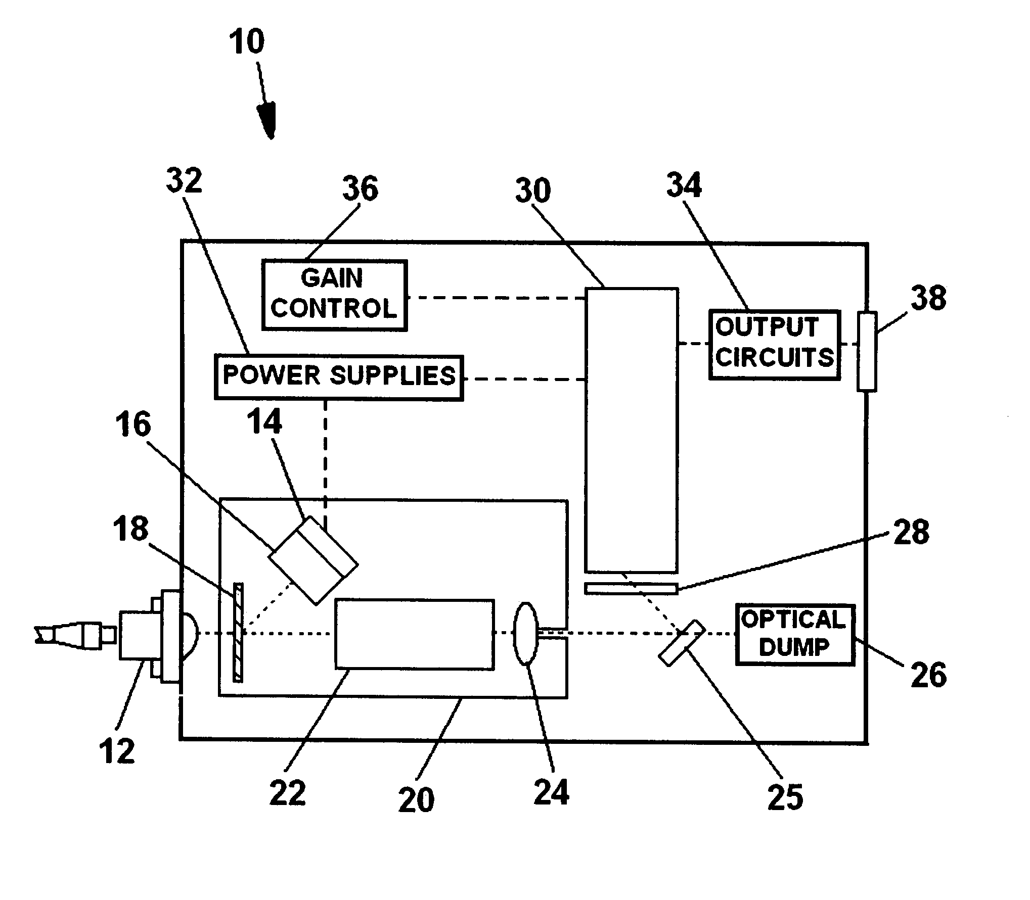
[0013]The sensor can also include various optical components such as lenses, mirrors, and gratings to form and direct the beams. Other components can be limiters for the signal input and for the power from the laser pump, which may be necessary to protect the photodetector from damage.
[0014]The present invention thereby provides a robust infrared sensor that has high sensitivity, low noise, high efficiency, and long life and is approximately the size of a cigarette pack.

Problems solved by technology

Low power infrared radiation is very difficult to detect and use electronically because sensitive photodetectors, such as photomultiplier and image intensifier tubes, which convert radiation into electrical signals, have very low sensitivity in the infrared region of the spectrum.

Method used


Image

  • Integrated ultra-sensitive infrared sensor
  • Integrated ultra-sensitive infrared sensor
  • Integrated ultra-sensitive infrared sensor

Examples


Embodiment Construction

[0017]FIG. 1 is a block diagram and FIG. 2 is a simplified layout diagram of the assembly of the preferred embodiment of infrared sensor 10 of the invention. Components visible in the assembly of FIG. 2 are identified by the same numbers as in FIG. 1.

[0018]Input apparatus 12 is an optical assembly when the incoming infrared signal arrives from free space, and is a connector for optical fiber (see FIG. 2) when the infrared signal is delivered by means of a cable of optical fibers. The incoming infrared signal processed by infrared sensor 10 can be in the range of between 0.8 μm and 5 μm with the proper selection of components that are described below.

[0019]Laser pump 14 is a laser diode chip generating a laser beam of a specific wavelength. In the preferred embodiment of the invention the wavelength generated is 808 nanometers (nm) for use with an incoming signal of 1550 nm. Thermoelectric cooler 15 is used to control the temperature of laser pump 14 to compensate for environmental t...


PUM


Abstract

The apparatus is a miniature assembly which detects very low power infrared radiation and produces an electronic signal. The incoming infrared is combined in a wavelength multiplexer with high energy light from a laser chip and passed through an upconversion crystal (a nonlinear optical crystal) in which their frequencies are added together. The higher frequency, lower wavelength, light is then directed to a miniature blue sensitive photomultiplier tube that generates an electrical signal. A thermoelectric cooler is used to control the temperature of the laser chip, and the entire device is assembled into a package which is approximately the size of a cigarette pack.

Description

[0001]This application claims the benefit of provisional patent application 60 / 816,836 filed Jun. 27, 2006.BACKGROUND OF THE INVENTION[0002]This invention deals generally with infrared sensors and more specifically with a miniaturized assembly which detects very low power infrared radiation and converts it into a usable electrical signal.[0003]Low power infrared radiation is very difficult to detect and use electronically because sensitive photodetectors, such as photomultiplier and image intensifier tubes, which convert radiation into electrical signals, have very low sensitivity in the infrared region of the spectrum.[0004]One technique which has been used to overcome this low infrared sensitivity has been the use of special phosphor materials external to the photosensitive tubes. Such materials upconvert, that is, they generate higher frequency and shorter wavelength radiation when stimulated by the infrared radiation, and the higher frequency radiation can then be accommodated b...

Claims


Application Information

Patent Timeline
IPC IPC(8): G01J5/00G01J4/00G01J5/02
CPCG01J1/02G01J1/0204G01J1/0228G01J1/0252G01J1/08G01J1/4257G01J1/58
Inventor HERR, DOUGLAS A.
Owner LEPTON TECH
Learn More