Aerosol generators and methods for producing aerosols
a technology of aerosol generator and generator, which is applied in the direction of respirator, transportation and packaging, rigid container, etc., can solve the problems of affecting the effectiveness of the generator, affecting the effect of the generator, and affecting the ability of the generator to work
- Summary
- Abstract
- Description
- Claims
- Application Information
AI Technical Summary
Benefits of technology
Problems solved by technology
Method used
Image
Examples
example 1
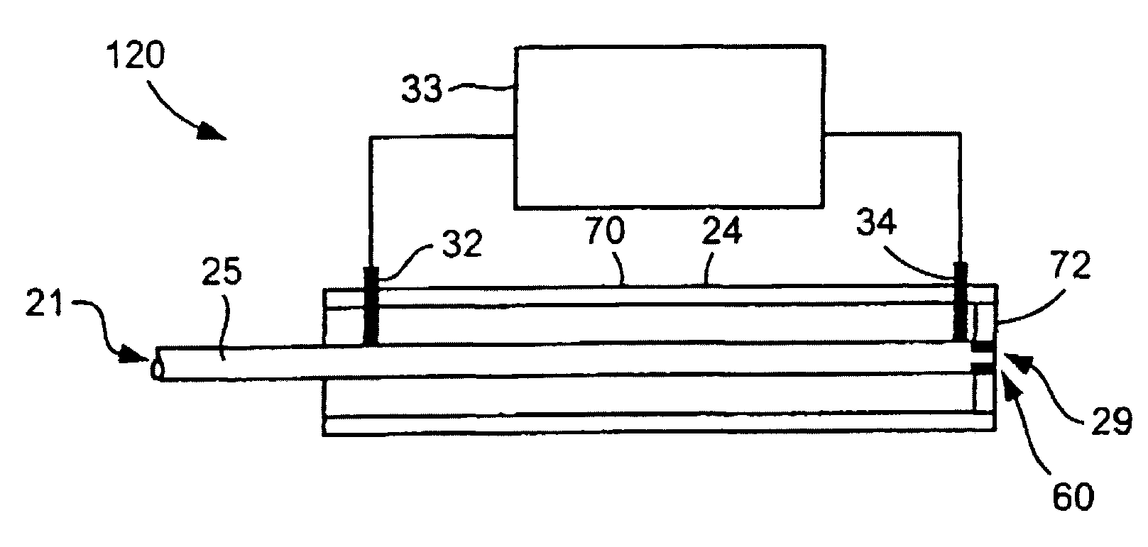
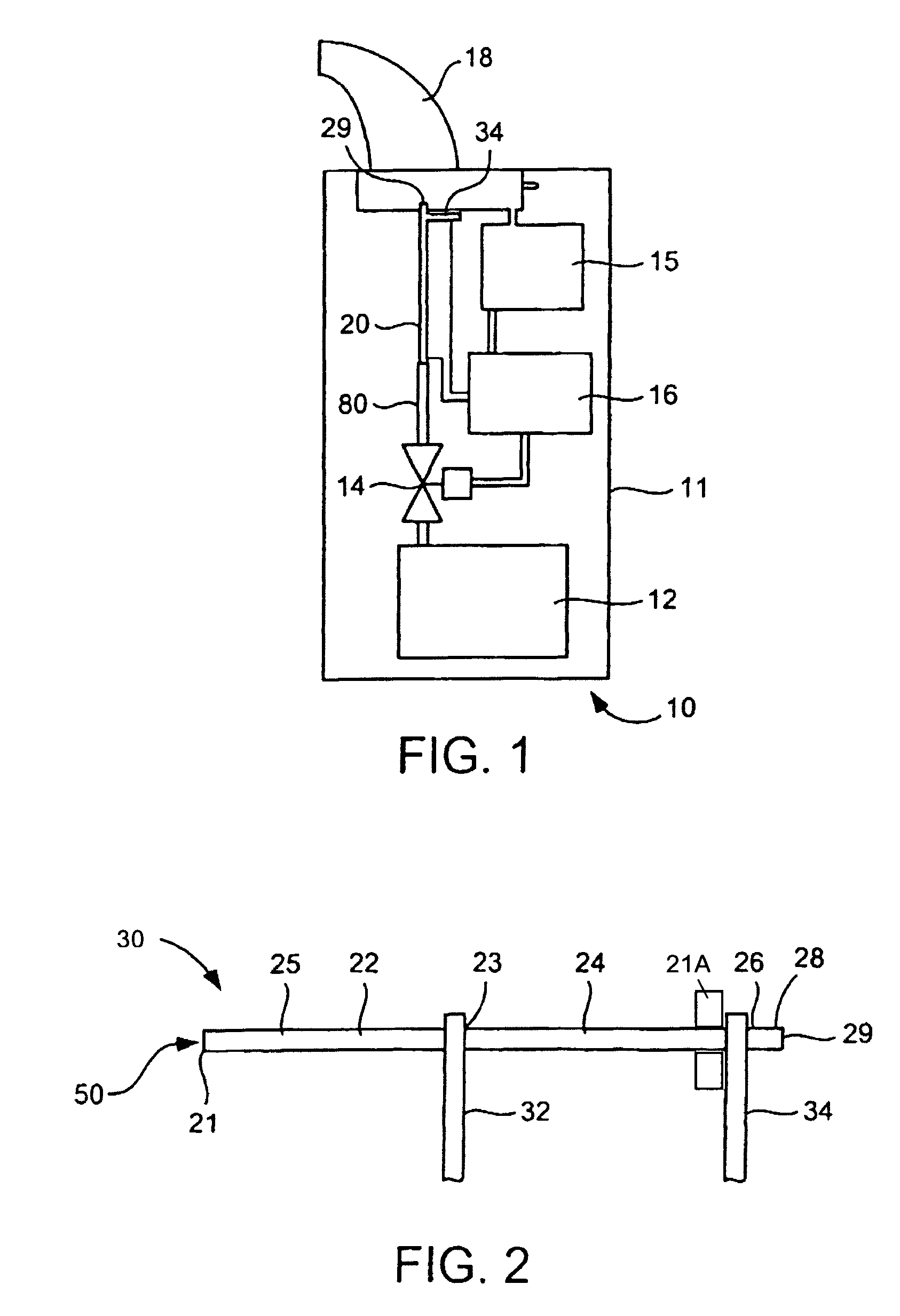
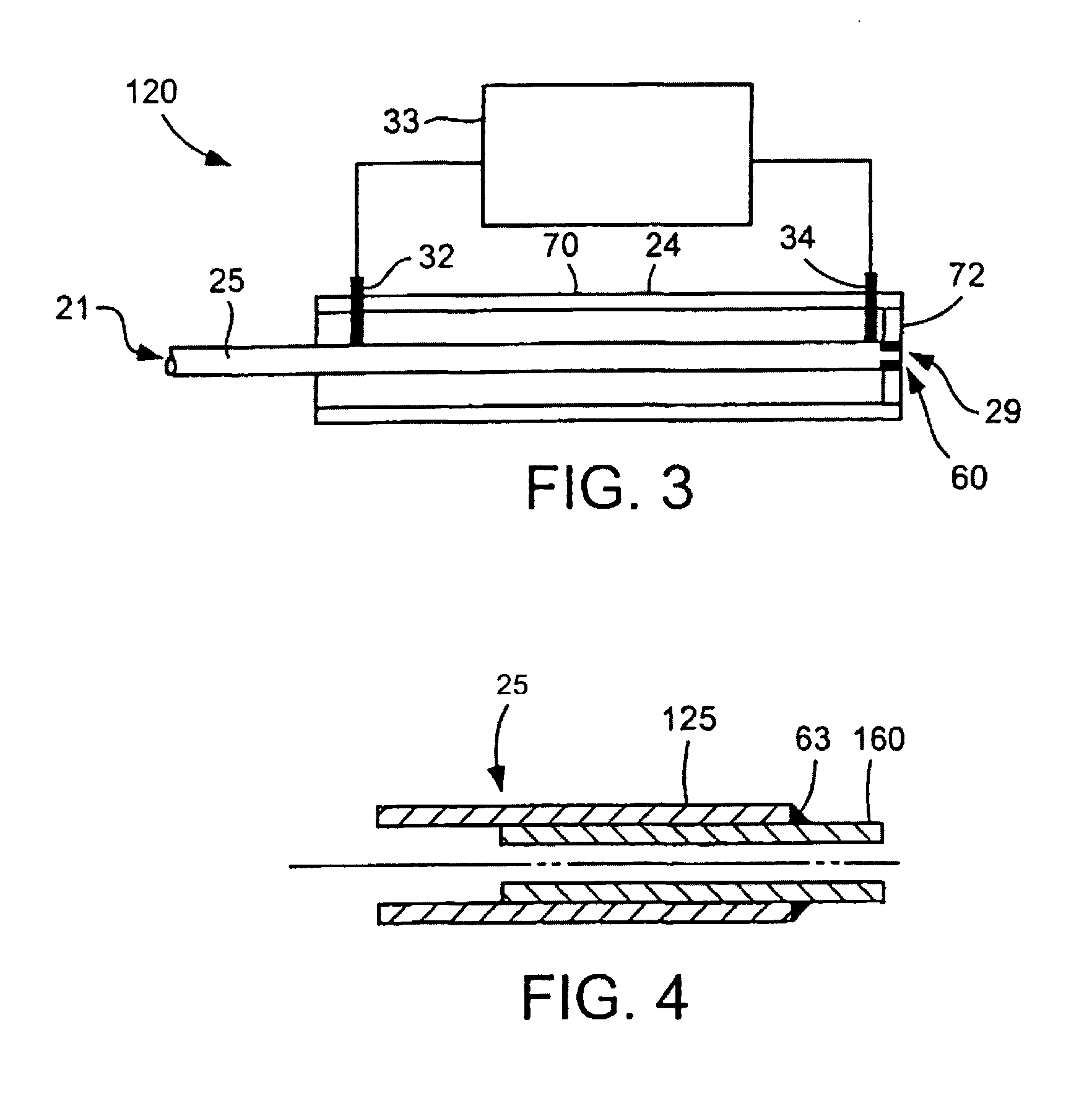
[0082]Tests were conducted to evaluate the influence on aerosol production of installing an insert in the flow passage of a CAG heater for producing aerosols from different liquid formulations including a high-volatility carrier, i.e., ethanol / water. The evaluation was conducted by comparing the performance of a CAG heater with no constriction untipped CAG) to that of a CAG heater having a constriction (tipped CAG). The CAG heater included a flow passage of K32EG tubing with an inner diameter of about 0.006 in (about 150 microns), a cross-sectional flow area of about 18,000 micron2 and a length of 35 mm. The CAG heater did not include a sleeve or cap.
[0083]In a test, a liquid formulation containing 1% albuterol sulfate in 80% ethanol / 20% water was supplied to the flow passage at a flow rate of 5 μL / sec. The % of actual metered dose of the albuterol sulfate recovered versus the applied power to the CAG heater was determined. The aerosol particles were collected using a particle colle...
example 2
[0089]Tests were conducted to evaluate the influence on aerosol recovery of varying the length of the flow passage of the CAG heater. The CAG heater included a flow passage with a constriction in the form of a 35 gauge tube insert at the outlet end. The CAG heater did not include a shield or cap. A liquid formulation containing 1.5% buprenorphine HCl in 95% ethanol / 5% water was supplied to the flow passage at a flow rate of 10 μL / sec.
[0090]In a first series of tests, the flow passage was a 30 gauge capillary tube having an inner diameter of about 0.006 in and a cross-sectional flow area of about 18,000 μm2. Different capillary tube lengths of 25, 30 and 35 mm were tested. In a second test, the flow passage was of K32EG tubing having a length of 25 mm. The test results for the % of actual metered dose of the buprenorphine HCl recovered versus the applied power to the CAG heater for the different capillary passage lengths are shown in FIG. 16. The % buprenorphine HCl recovery on the f...
example 3
[0091]Tests were conducted to evaluate the influence on aerosol production of varying the length of the constriction of the CAG heater. The CAG heater included a flow passage of K32EG tubing having a length of 35 mm. Constrictions in the form of 35 gauge tube inserts having lengths of 3 mm, 4 mm, 5 mm and 6 mm were separately installed at the outlet end of the flow passage. The CAG heater did not include a sleeve or cap. A liquid formulation containing 1.5% buprenorphine HCl in 95% ethanol / 5% water was supplied to the flow passage at a flow rate of 10 μL / sec. FIG. 17 shows the test results for the % of actual metered dose of the buprenorphine HCl recovered on a filter versus the applied power to the CAG heater. The % recovery on the filter was at least about 78% for the different insert lengths. The recovery was not significantly changed by increasing the constriction length. These test results demonstrate that CAG heaters including a constriction in the capillary flow passage can p...
PUM
 Abstract
Description
Claims
Application Information
 - R&D
- Intellectual Property
- Life Sciences
- Materials
- Tech Scout
- Unparalleled Data Quality
- Higher Quality Content
- 60% Fewer Hallucinations
Browse by: Latest US Patents, China's latest patents, Technical Efficacy Thesaurus, Application Domain, Technology Topic, Popular Technical Reports.
© 2025 PatSnap. All rights reserved.Legal|Privacy policy|Modern Slavery Act Transparency Statement|Sitemap|About US| Contact US: help@patsnap.com


