
High bandwidth one time field-programmable memory

a one-time field, high-bandwidth technology, applied in static storage, digital storage, instruments, etc., can solve the problems of limiting system performance, program disturbance, read disturbance, and restricted endurance of steering elements, so as to reduce voltage levels and reduce leakage currents through arrays

Active Publication Date: 2009-03-03
SANDISK TECH LLC
View PDF89 Cites 73 Cited by
  • Summary
  • Abstract
  • Description
  • Claims
  • Application Information

AI Technical Summary

Benefits of technology

The patent text describes a type of memory cell that can be programmed once during manufacturing. This cell has a resistance change element and a steering element. The cell can be programmed by applying a reverse bias operation, which reduces leakage currents and voltage levels. The memory cells can be fabricated by switching them from a virgin state to a resistance state during manufacturing. The programmed state of the cell can be restored to its initial state by applying a reverse bias. The technical effect of this patent is to provide a reliable and efficient way to program non-volatile memory cells during manufacturing.

Problems solved by technology

High bias conditions applied to program these cells can restrict the endurance of the steering element.
High leakage currents, program disturbances, read disturbances, etc. can pose difficulties when attempting to produce a memory device comprising one or more arrays of passive element memory cells that can be reliably fabricated, programmed, and read.
These factors often limit system performance by reducing the number of cells that can be simultaneously addressed in order to keep leakage currents at acceptable levels, for example.
Such limitations on bandwidth may prove unacceptable in certain applications.

Method used


Image

  • High bandwidth one time field-programmable memory
  • High bandwidth one time field-programmable memory
  • High bandwidth one time field-programmable memory

Examples


Embodiment Construction

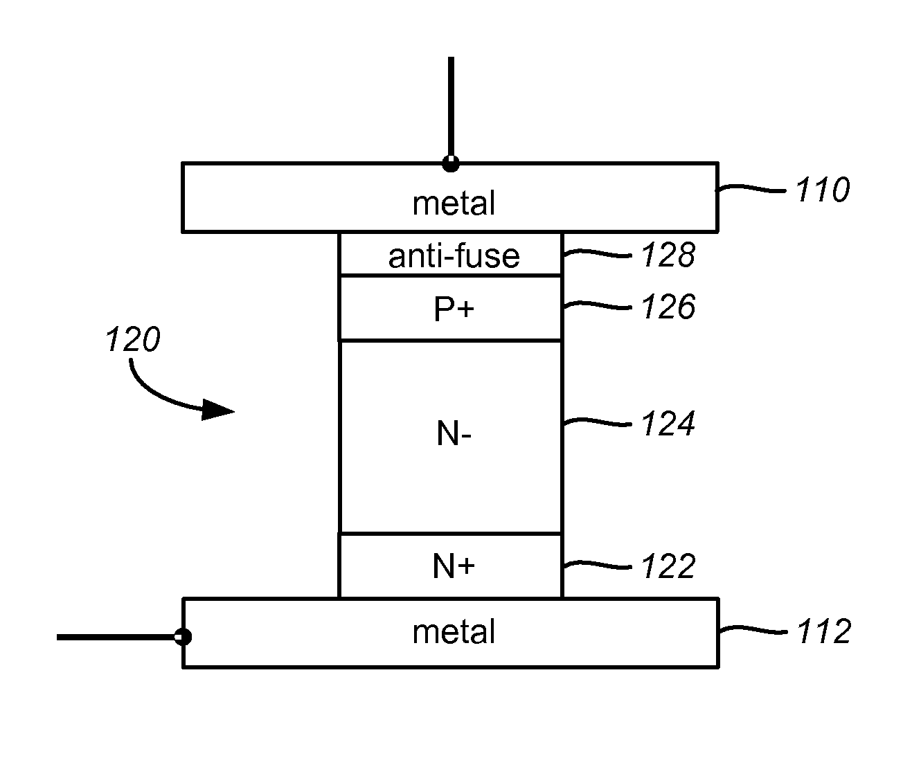
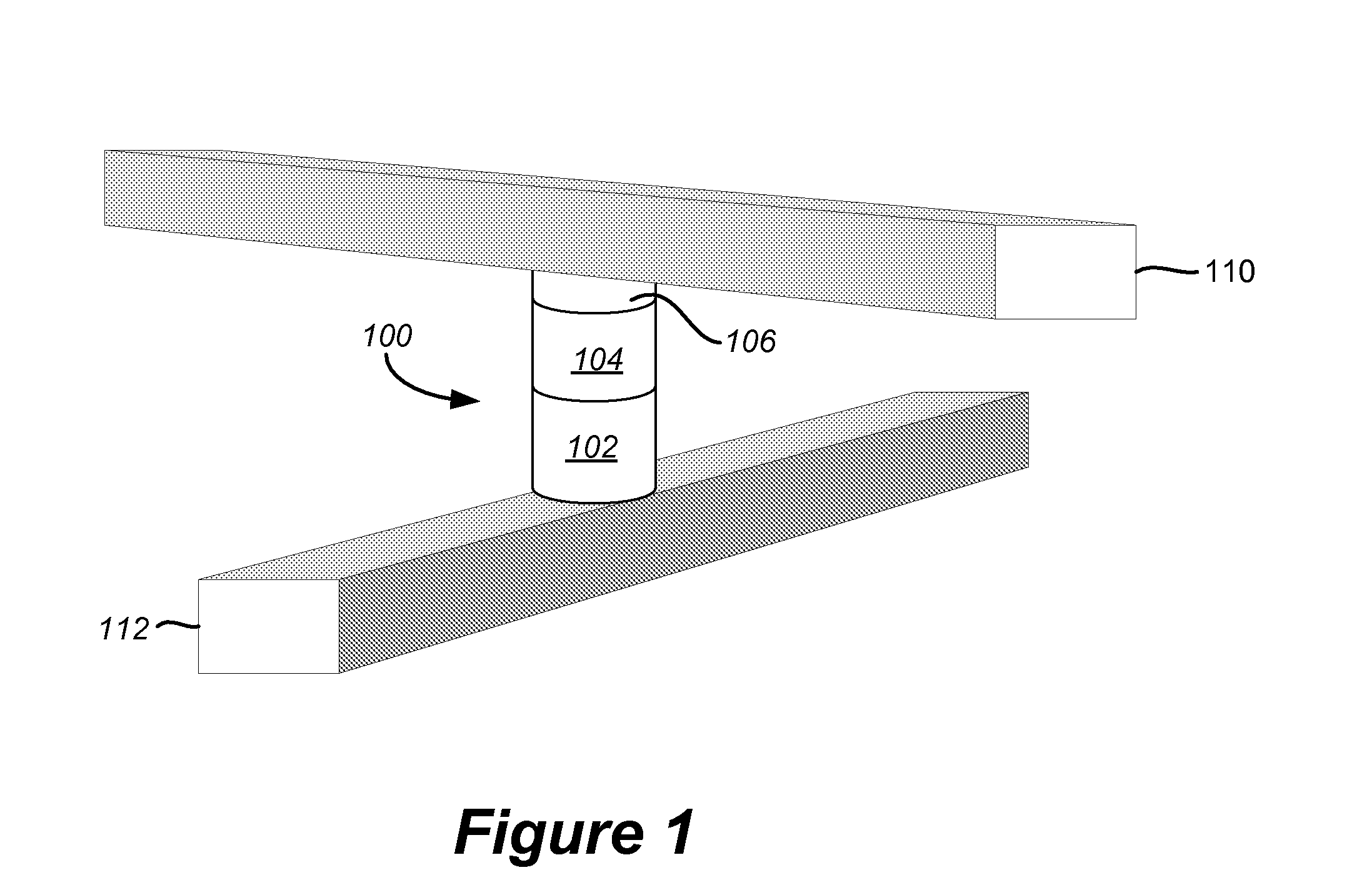
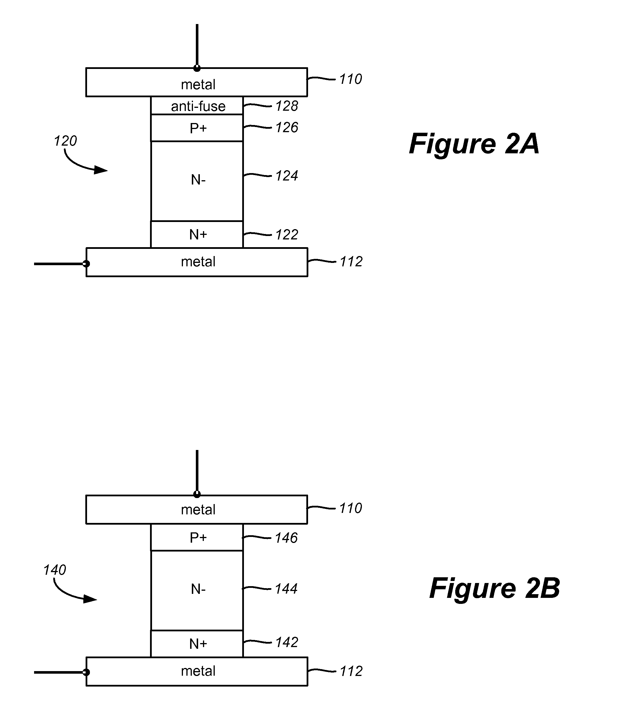
[0047]FIG. 1 depicts an exemplary structure for a non-volatile memory cell that can be used in accordance with embodiments of the present disclosure. A two-terminal memory cell 100 as depicted in FIG. 1 includes a first terminal portion connected to a first conductor 110 and a second terminal portion connected to a second conductor 112. The memory cell includes a steering element 102 in series with a state change element 104 and an anti-fuse 106 to provide non-volatile date storage. The steering element can take the form of any suitable device exhibiting a nonlinear conduction current characteristic such as a simple diode. The state change element will vary by embodiment and can include numerous types of materials to store data through representative physical states. State change element 104 can include resistance change materials, phase change resistive materials, etc. For example, a semiconductor or other material having at least two levels of detectable resistance change (e.g., l...


PUM


Abstract

A one-time field programmable (OTP) memory cell with related manufacturing and programming techniques is disclosed. An OTP memory cell in accordance with one embodiment includes at least one resistance change element in series with a steering element. The memory cell is field programmed using a reverse bias operation that can reduce leakage currents through the array as well as decrease voltage levels that driver circuitry must normally produce in program operations. An array of memory cells can be fabricated by switching the memory cells from their initial virgin state to a second resistance state during the manufacturing process. In one embodiment, the factory switching operation can include popping an anti-fuse of each memory cell to set them into the second resistance state. The array of memory cells in the second resistance state are provided to an end-user. Control circuitry is also provided with the memory array that can switch the resistance of selected cells back toward their initial resistance state to program the array in accordance with data received from a user or host device.

Description

CROSS-REFERENCE TO RELATED APPLICATIONS[0001]The following related applications, filed on even date herewith, are cross-referenced and incorporated by reference herein in their entirety:[0002]U.S. patent application Ser. No. 11 / 461,393, entitled “Controlled Pulse Operations in Non-Volatile Memory,” filed concurrently;[0003]U.S. patent application Ser. No. 11 / 461,399, entitled “Systems for Controlled Pulse Operations in Non-Volatile Memory,” filed concurrently;[0004]U.S. patent application Ser. No. 11 / 461,419, entitled “Systems For High Bandwidth One Time Field-Programmable Memory,” by Roy E. Scheuerlein and Christopher J. Petti;[0005]U.S. patent application Ser. No. 11 / 461,424, entitled “Reverse Bias Trim Operations in Non-Volatile Memory,” by Roy E. Scheuerlein and Tanmay Kumar;[0006]U.S. patent application Ser. No. 11 / 461,431, entitled “Systems for Reverse Bias Trim Operations in Non-Volatile Memory,” by Roy E. Scheuerlein and Tanmay Kumar;[0007]U.S. patent application Ser. No. 11...

Claims


Application Information

Patent Timeline
Patent Type & Authority Patents(United States)
IPC IPC(8): G11C11/00
CPCG11C5/145G11C5/147G11C7/12G11C8/06G11C8/08G11C8/12G11C11/5692G11C13/0023G11C13/0026G11C13/0028G11C13/003G11C13/0038G11C17/16G11C17/165G11C17/18G11C2213/71G11C2213/72G11C2213/74
Inventor SCHEUERLEIN, ROY E.PETTI, CHRISTOPHER J.
Owner SANDISK TECH LLC
Learn More