
Method of and control switch arrangement for controlling different operational states in an electro-optical reader

a technology of control switch and operation state, applied in the field of electronic readers, can solve the problems of difficult aiming of the head relative to the symbol, non-readily visible laser diode light, and inability of users to readily aim laser diode light at the symbol, etc., and achieve the effect of improving the performance of the reader

Active Publication Date: 2009-03-03
SYMBOL TECH LLC
View PDF3 Cites 11 Cited by
  • Summary
  • Abstract
  • Description
  • Claims
  • Application Information

AI Technical Summary

Benefits of technology

[0013]One object of this invention is to provide an improved control switch arrangement for and method of controlling different operational states for improving performance of a reader for reading a data-encoded symbol.
[0014]Another object of this invention is to provide a control switch arrangement which is compact, lightweight, durable and efficient in construction and quiet and reliable in operation, and thus is ideally suited for portable hand-held applications.
[0019]Using an FSR switch enables a low actuation force to be used, typically from 0.2 to 1.0 Newtons, which is much less than the force required for a conventional tactile switch, typically 1.4 Newtons. Using an FSR switch also enables a minimal travel stroke, typically on the order of less than hundredths of a millimeter. This also means that the second stroke to initiate the control switch can be made longer to better ergonomically distinguish between actuation of the switches.
[0022]In accordance with this invention, the FSR switch enables actuation at very low actuation forces and over a very short travel stroke. A greater travel stroke can be designed to actuate the control switch, even with a shorter travel stroke for the control switch, thereby enabling ergonomic efficiency and differentiation between the FSR and the control switches.

Problems solved by technology

However, in the event that the laser light beam was generated by a semiconductor laser diode, as, by way of example, see U.S. Pat. Nos. 4,387,297; 4,409,470 and 4,460,120, then the aiming of the head relative to the symbol was rendered more difficult when the laser diode emitted laser light which was not readily visible to the user.
Furthermore, if the laser diode light was moving, for example, by being swept across the symbol, and especially if the laser diode light was being swept at fast rates of speed on the order of a plurality of times per second, for example, at a rate of 40 scans per second, then the laser diode light was not readily visible to the user, even in a darkened room.
This non-readily visible laser diode light did not enable the user, however, to readily aim the laser diode light at the symbol, at least not without some difficulty and practiced effort because, simply put, the user could not see the laser diode light.
This hunting technique was a less-than-efficient and time-consuming procedure for reading symbols, particularly in those applications where a multitude of symbols had to be read every hour and every day.
However, the known double-action switches are not altogether satisfactory from an ergonomic point of view and typically require a long travel stroke between actuations of the switches, as well as some sort of positive tactile feedback for at least one of the switches, and also require a relatively high actuation force to control the switches.
All of these factors, plus the lack of availability of high precision switches capable of very long working lifetimes, have proven disadvantageous in making such readers as ergonomically efficient as possible.

Method used


Image

  • Method of and control switch arrangement for controlling different operational states in an electro-optical reader
  • Method of and control switch arrangement for controlling different operational states in an electro-optical reader
  • Method of and control switch arrangement for controlling different operational states in an electro-optical reader

Examples


Embodiment Construction

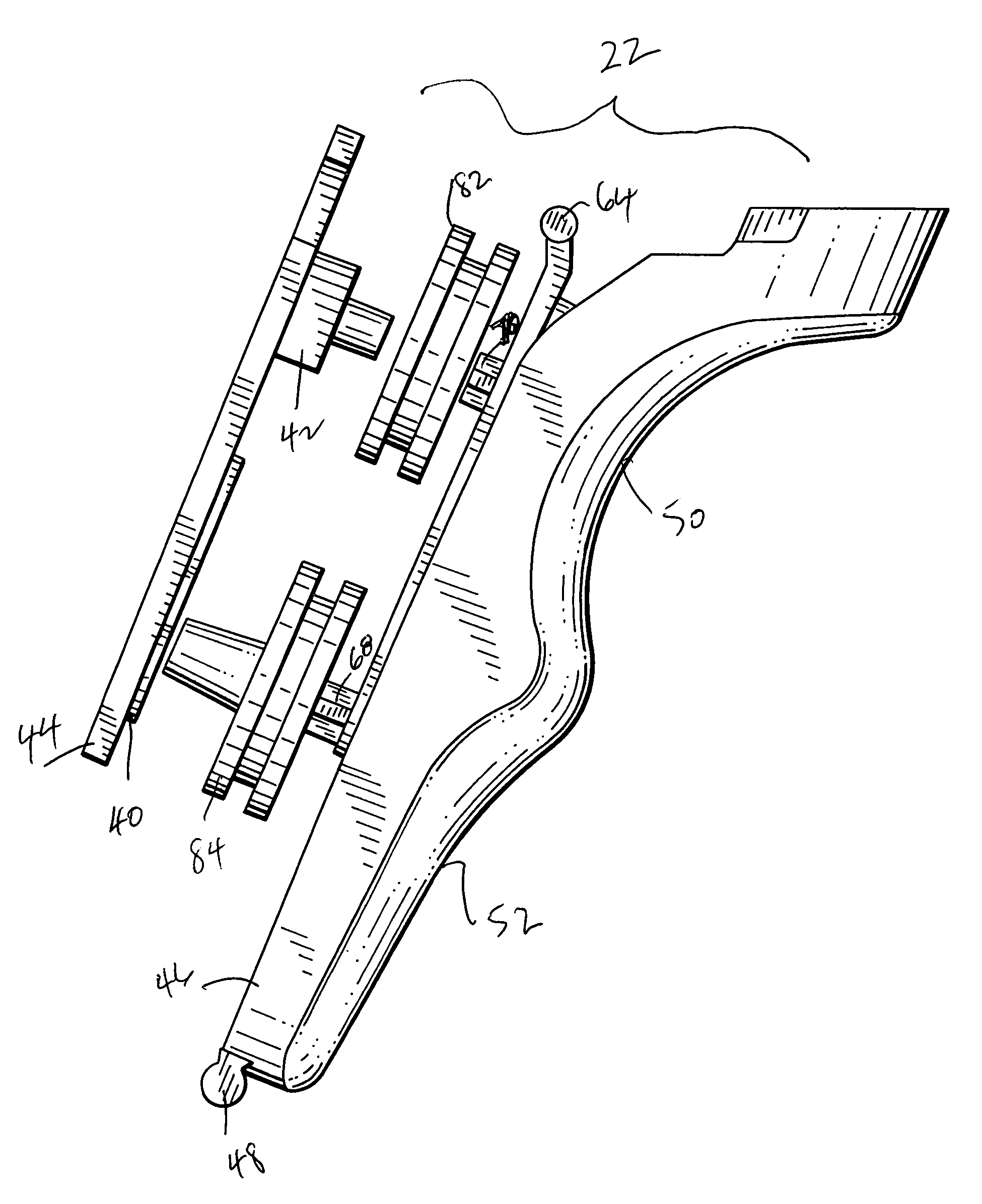
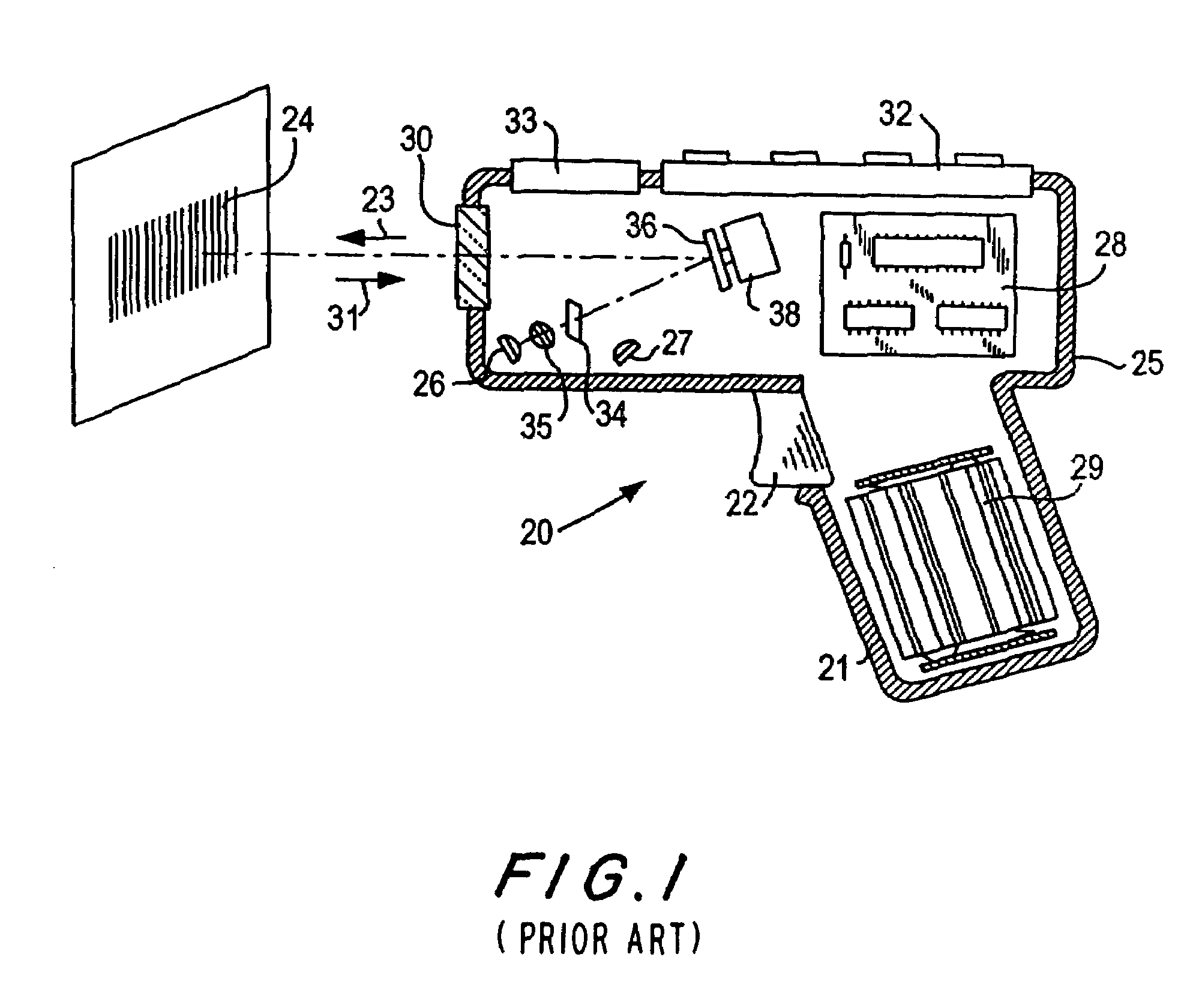
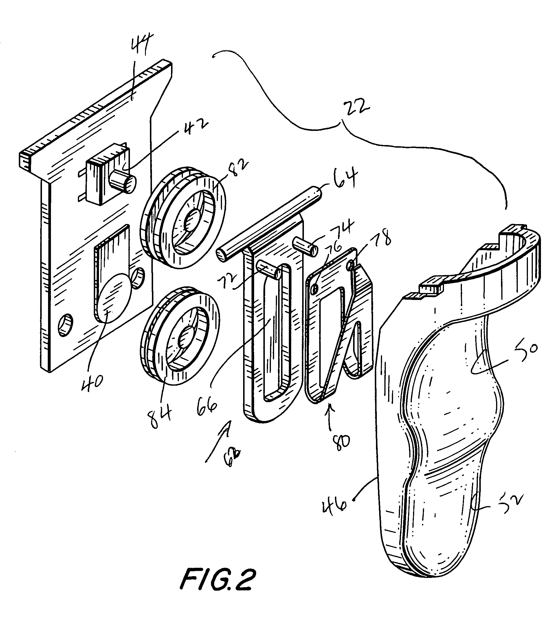
[0030]Reference numeral 20 in FIG. 1 generally identifies a hand-held reader for electro-optically reading indicia, such as bar code symbol 24, located in a range of working distances therefrom. The reader 20 has a pistol grip handle 21 and a manually actuatable trigger 22 which, when depressed, enables a light beam 23 to be directed at the symbol 24. The reader 20 includes a housing 25 in which a light source 26, a light detector 27, signal processing circuitry 28, and a battery pack 29 are accommodated. A light-transmissive window 30 at a front of the housing enables the light beam 23 to exit the housing, and allows light 31 scattered off the symbol to enter the housing. A keyboard 32 and a display 33 may advantageously be provided on a top wall of the housing for ready access thereto.

[0031]In use, an operator holding the handle 21 aims the housing at the symbol and depresses the trigger. The light source 26 emits a light beam which is optically modified and focused by an optical ...


PUM


Abstract

A control switch arrangement for sequentially controlling different operating states in a moving beam reader or an imager employs a force sensing resistor switch requiring a low actuation force, and a control switch with improved tactile feedback and ergonomic efficiency between the switches.

Description

BACKGROUND OF THE INVENTION[0001]1. Field of the Invention[0002]The present invention generally relates to electro-optical readers for reading indicia, for example, bar code symbols, having parts with different light reflectivities and, in particular, to a control switch arrangement for, and a method of, controlling different operational states in such readers.[0003]2. Description of the Related Art[0004]Various electro-optical readers have previously been developed for reading bar code symbols appearing on a label, or on a surface of a target. The bar code symbol itself is a coded pattern of indicia. Generally, the readers electro-optically transform graphic indicia of the symbols into electrical signals which are decoded into alphanumeric characters. The resulting characters describe the target and / or some characteristic of the target with which the symbol is associated. Such characters typically comprise input data to a data processing system for applications in point-of-sale pro...

Claims


Application Information

Patent Timeline
Patent Type & Authority Patents(United States)
IPC IPC(8): G06K7/10
CPCG06K7/10851G06K7/10881
Inventor MITELMAN, YULYGIORDANO, JOSEPHPAI, AMIT
Owner SYMBOL TECH LLC
Learn More