
Quadrapod air assisted catamaran boat or vessel

a catamaran and quadripod technology, applied in the field of catamaran boats or vessel hulls, can solve the problems of craft's hull falling into the water, affecting the safety of passengers, and unable to properly dispose of the pressurized air cushion to allow the use of water jet propulsors, etc., to reduce the resistance of the forward and aft hull sections, reduce the wake, and reduce the amount of power

Inactive Publication Date: 2009-03-03
GLOBAL MARITIME SOLUTIONS
View PDF4 Cites 5 Cited by
  • Summary
  • Abstract
  • Description
  • Claims
  • Application Information

AI Technical Summary

Benefits of technology

[0010]The mid-length portion of each catamaran hull has a cavity formed therein, the cavity extending rearward from the step of the bow portion, to the intersection with the aft hull portion at the intersection of the aft hull portion and the chine's, and inwardly from the exterior surface of the sides. The top portion of the cavity is formed by a horizontal plane parallel to the keel. A pressurized air generation means that is well known in the art is connected in fluid flow communication with the air cushion cavity to provide hull lift.
[0012]Fins or skegs are incorporated between the forward and aft hull sections on each side of each hull at each chine to guide the water flow under the boat or vessel to retain air within the cavity portion of the hull. The enclosure of the air cavity allows air or gas to mechanically be induced to create a pressure that will lift the vessel in order to reduce the resistance of the forward and aft hull sections thereby reducing the amount of power required to drive the design at a specified speed. The end of each fin at the terminus with the intersection of the aft hull with the chine allows the air to be released from the cavity in a way as to prevent interaction with water jet propulsors and also to reduce the wake generated by the boat or vessel hull.

Problems solved by technology

The prior art of air cushion vessel hull designs include the Harley patent (U.S. Pat. No. 5,570,612) which eliminated the use of flexible seals to contain the air cushion, but this prior art did not properly dispose of the pressurized air cushion to allow for the use of water jet propulsors.
The flexible seals reduce the amount of air lost from the air cushion but create a rough ride even in smooth water.
Also, in rough water the flexible seals frequently fail to maintain the air cushion, causing the craft's hull to drop lower into the water until the seal is regained and the air cushion is reestablished.
The loss of the air cushion increases the hull contact with the water increasing the hull-to-water friction and significantly slowing the vessel.
Seals are a high maintenance problem with frequent breakage that results in permanent loss of air cushion and a slow ride to the repair yard.

Method used


Image

  • Quadrapod air assisted catamaran boat or vessel
  • Quadrapod air assisted catamaran boat or vessel
  • Quadrapod air assisted catamaran boat or vessel

Examples


Embodiment Construction

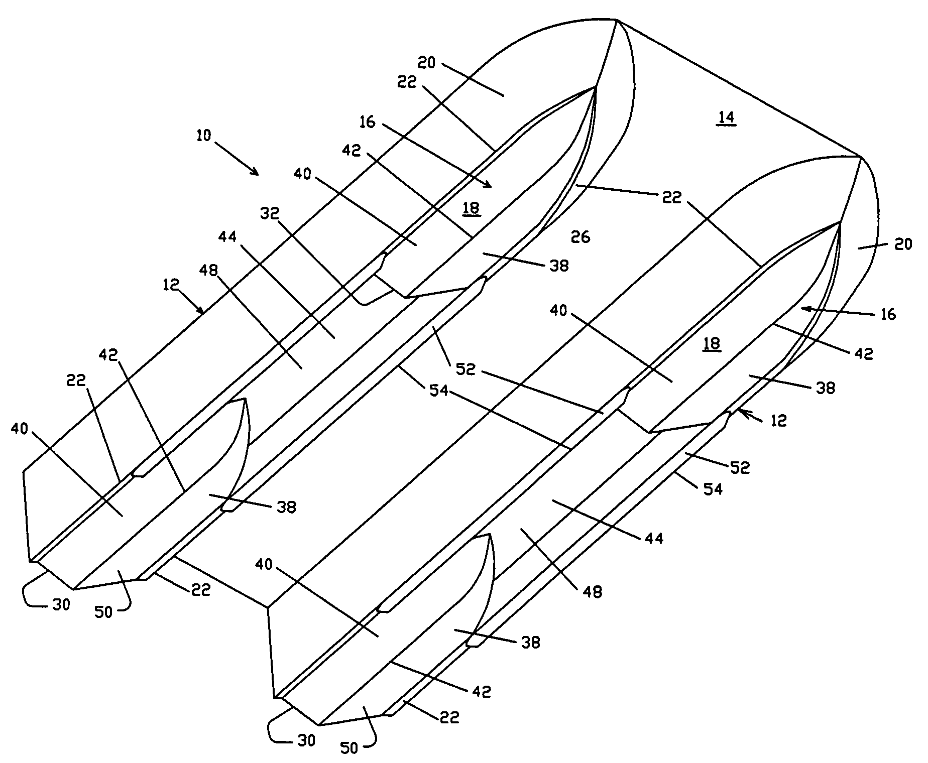
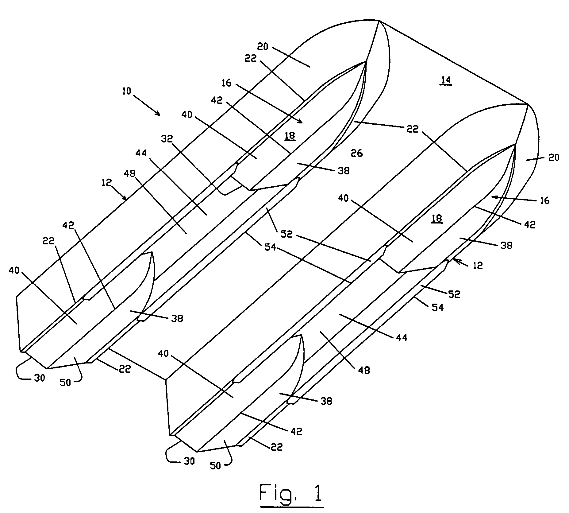
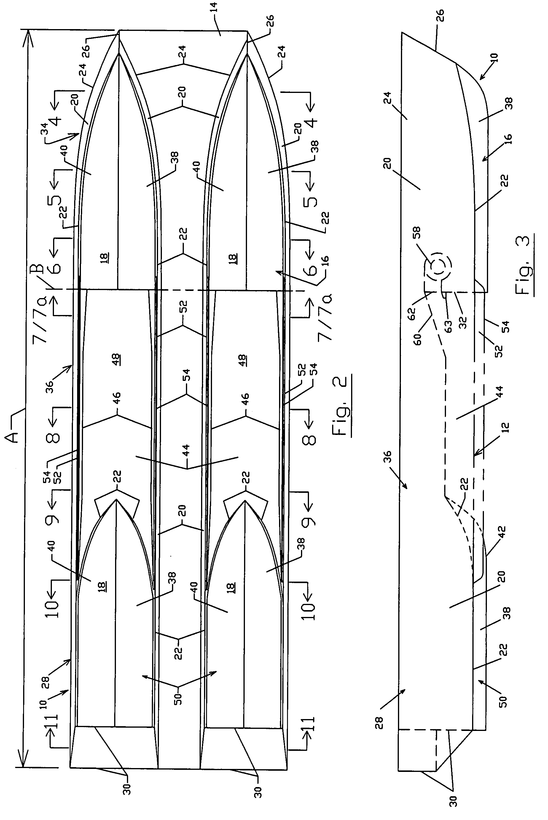
[0028]A preferred embodiment for the quadra-pod hull is illustrated in the drawing FIGS. 1-11 in which the vessel is generally indicated as 10. Referring first to FIG. 1 it can be seen that the vessel hull 10 comprises a pair of catamaran hulls 12 that are joined to one another by a deck or cross structure 14.

[0029]As shown in FIG. 2, each catamaran hull has a longitudinal dimension, and comprises a bottom 16, that has exterior surfaces 18, a pair of opposing sides 20 that are attached to the bottom 16 and extend upwardly there from. For the purposes of this specification, the chine 22 defines the line of attachment of the sides 20 to the bottom 16. The first ends 24 of each side 20 are joined to form the bow 26, the second mid-length sections 36, and the third ends 28 are connected to one another by a transom 30 that extend transversely there between. A step 32, extends inwardly from the bottom 12, which can be seen most clearly in FIGS. 3 and 7, extends inwardly from the bottom 12...


PUM


Abstract

A twin-hull catamaran boat or vessel comprising of four hydrodynamic pod sections connected with a mid-span recess on each hull that receives mechanically inducted gas or air for hull support. Each hull shape of the twin-hull catamaran configuration contains one V-shaped hull portion forward (bow), one mid-length hull cavity portion that receives pressurized gas or air therein (amidships), and one V-shaped hull portion aft (stern). The V-shaped bow portion creates hydrodynamic lift, the air or gas mechanically pressurized mid-length recess portion creates an air cushion to lift the hull in order to reduce wetted surface and drag on the hulls, and the V-shaped stern portion provides hydrodynamic lift to support the aft portion of the twin-hull catamaran configuration and also to provide an aft sealing body for the mechanically pressurized air or gas mid-length cavity. The benefit of the hull configuration as described herein results in lower resistance and uses less horsepower to attain a specific boat or vessel speed.

Description

RELATED APPLICATIONS[0001]This application claims priority to U.S. Provisional Patent Application Ser. No. 60 / 845,017 filed Sep. 15, 2006.BACKGROUND OF THE INVENTION[0002]1. Field of the Invention[0003]The present invention relates to marine boats or vessel hulls utilizing a conventional twin-hull catamaran boat or vessel configuration with a mid-length cavity wherein pressurized air or gas is mechanically induced to provide vessel lift for reduction of total water drag on the hull, thereby reducing the power levels required to attain a specific design speed. This in-turn allows for a reduction of power levels for a given speed thereby reducing the fuel consumption of the designated propulsion units.[0004]2. Description of the Prior Art[0005]The primary objective in boat or vessel design is to reduce the amount of drag caused by the interaction of the hull with the water surface. Planing hulls are designed so that forward motion of the hull raises the vessel to cause it to ride on a...

Claims


Application Information

Patent Timeline
Patent Type & Authority Patents(United States)
IPC IPC(8): B63B1/00B63B1/32B63B1/38
CPCB63B1/121B63B1/38Y02T70/122Y02T70/10
Inventor DIZE, ANDREW P.
Owner GLOBAL MARITIME SOLUTIONS
Learn More