
Functional object data, functional object imaging system, and object data transmitting unit, object data receiving unit and managing unit for use in the functional object imaging system

a functional object and imaging system technology, applied in the field of functional object imaging system, can solve the problems of difficult for customers to clearly and intuitively grasp the various functions and effects of such combinations of functional resources, and it is difficult for customers to grasp the characteristic functions of that product, and it is difficult for customers to predict the function of a combination of functional resources based on the function of each resource.

Active Publication Date: 2009-02-24
FUJITSU LTD
View PDF14 Cites 13 Cited by
  • Summary
  • Abstract
  • Description
  • Claims
  • Application Information

AI Technical Summary

Benefits of technology

[0031]In a specific embodiment of the object data transmitting unit, which renders the effect of the invention striking, the functional object represents production equipment for producing a predetermined article to be produced or sold, or it represents the predetermined article to be produced or sold. Alternatively, the functional object may represent personnel including part-time workers and employees stationed in a layout space such as a factory, office or house, or an article including industrial machines, office equipment and furniture disposed in the layout space.
[0032]If a managing unit is provided comprising a recorded data receiving section for receiving data on utilization of functional objects at the object data receiving unit, it is possible to realize, for example, a more effective marketing activity by analyzing the data on utilization of functional objects received.
[0033]According to yet another aspect of the present invention, there is provided a functional object imaging system comprising an object data receiving unit and an object data transmitting unit, at least one of which is provided with a charging management section for conducting processing related to charging for utilization of functional objects. The functional object imaging system thus configured is capable of making charge for utilization of the functional objects in the system.

Problems solved by technology

It is, however, very difficult for customers to clearly and intuitively grasp various functions and effects of such combinations of functional resources even if a normal data list of each functional resource as described above and the like are presented.
With increasingly complicated and diversified requests of demanders for goods and services in these years, products having various options to realize diversified functions are increasing.
The diversity of functions of a product, contradictorily, makes it more difficult for the demanders to grasp the characteristic functions of that product.
That is, since actions and effects of functional resources of this type vary depending on combinations of such resources, environments and the like, it is difficult to predict the function of a combination of functional resources based simply on the function of each resource.
If functions of combinations of functional resources are to be simulated on a computer, a simulation program needs to be developed for each combination, which requires enormous time and labor and hence lacks rapid responsiveness.

Method used


Image

  • Functional object data, functional object imaging system, and object data transmitting unit, object data receiving unit and managing unit for use in the functional object imaging system
  • Functional object data, functional object imaging system, and object data transmitting unit, object data receiving unit and managing unit for use in the functional object imaging system
  • Functional object data, functional object imaging system, and object data transmitting unit, object data receiving unit and managing unit for use in the functional object imaging system

Examples


Embodiment Construction

[0061]The present invention will now be described in detail with reference to the drawings.

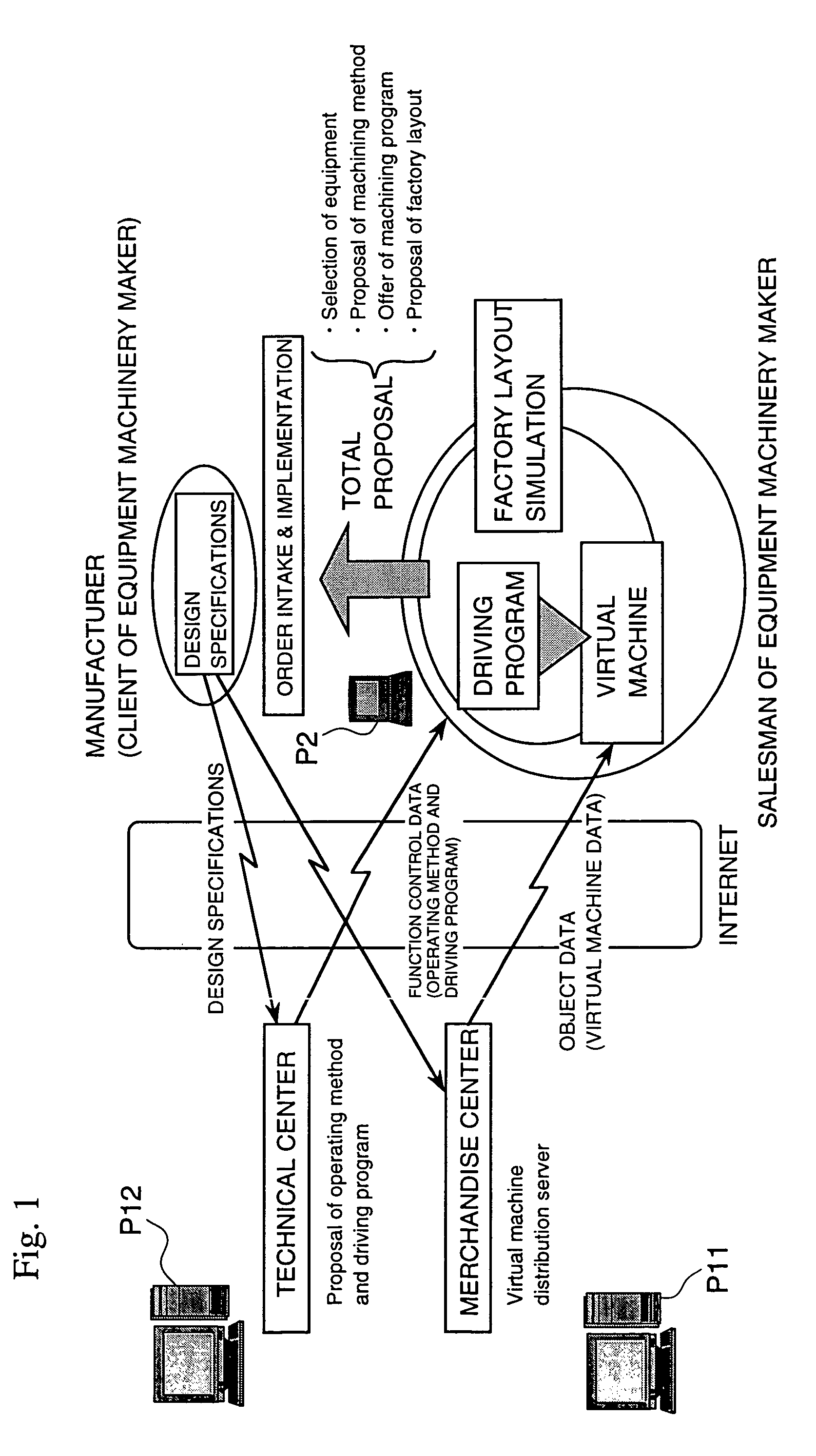
[0062]Referring first to FIG. 1, there is shown a system configuration of a functional object imaging system according to one embodiment of the present invention. In FIG. 1, reference character P11 denotes an object data transmitting unit for transmitting object data, for example, on a machining center (hereinafter referred to as “MC”) as one functional resource, while reference character P12 denotes an object data transmitting unit for transmitting object data on a recording medium (for example FDD) storing a MC control program as another functional resource that is incorporated in MC to cause MC to exhibit a predetermined function. These object data transmitting units P11 and P12 may be operated either by a same operator or by different operators. It is needless to say that the units P11 and P12 may be physically integral with each other. Reference character P2 denotes an object data receivi...


PUM


Abstract

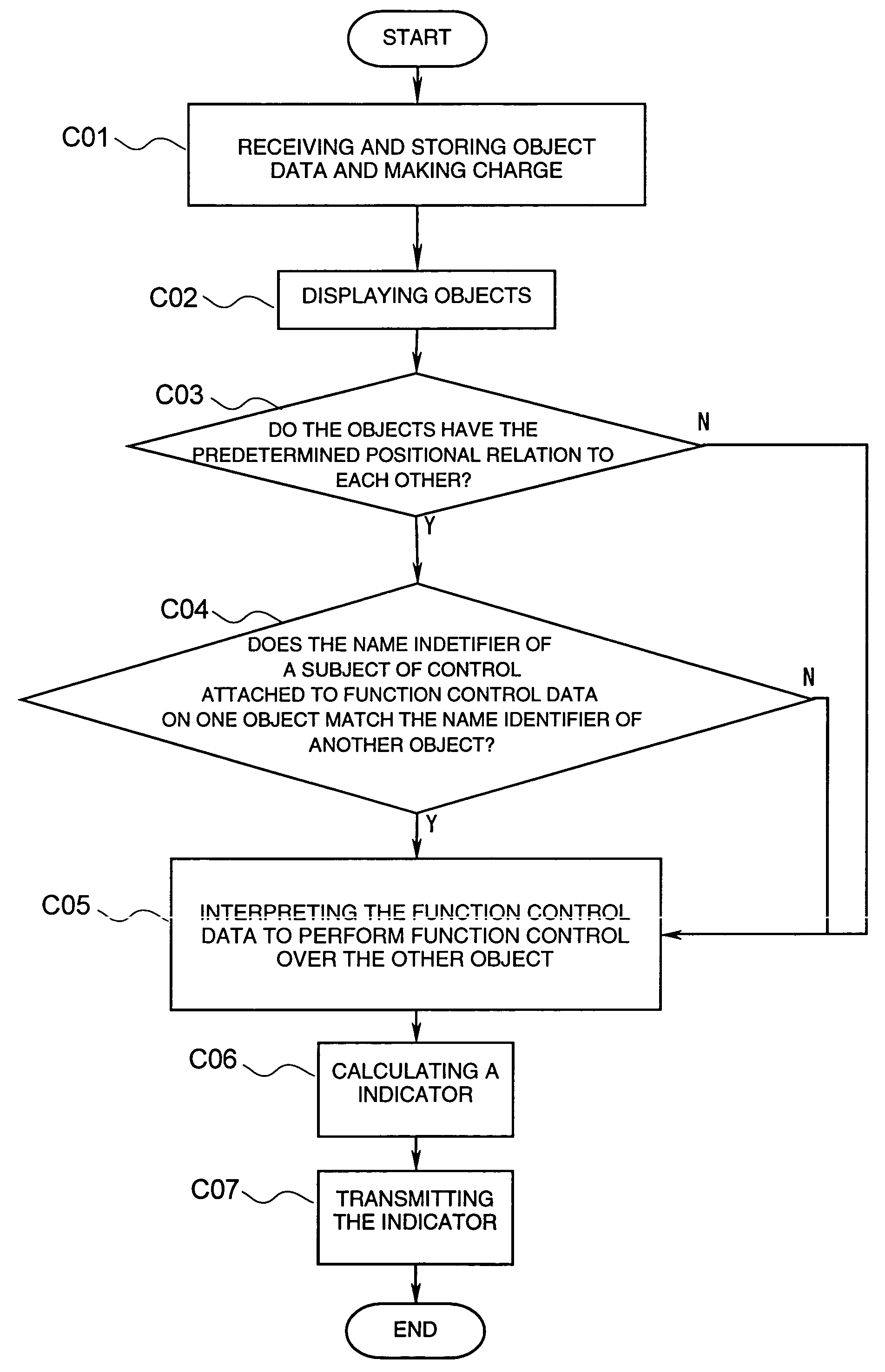
A functional object imaging system using functional object data is provided. The functional object data includes: at least imaging data for imaging functional resources as functional objects in a virtual space and name identifiers allocated to the respective functional objects, and optionally, function control data for provoking or creating a function of a functional object as a subject of control and a second name identifier allocated to the object as the subject of control, the functional object data having a structure to allow a computer to judge whether a relation between a name identifier allocated to a functional object having a predetermined relation to one functional object and a second name identifier allocated to the one functional object satisfies a predetermined condition, interpret function control data on the one functional object when the relation is judged to satisfy the predetermined condition, and control either directly or indirectly imaging data on the functional object having the predetermined relation to the one functional object based on the interpretation thus made to achieve function control over the functional object having the predetermined relation to the one functional object.

Description

CROSS REFERENCE TO RELATED APPLICATIONS[0001]This application is based upon and claims the benefit of priority from the prior Japan Patent Application Nos. P2002-226876, filed Aug. 5, 2002, and P2002-319164, filed Oct. 31, 2002, the entire contents of which are incorporated herein by reference.BACKGROUND OF THE INVENTION[0002]1. Field of the Invention[0003]The present invention relates to a functional object imaging system and the like for use in a system adapted to satisfy the specifications of a required article, service or the like by employing a plurality of functional resources exhibiting their respective functions. The functional object imaging system is configured to evaluate a production plan or its operation based on a combination of such functional resources in a virtual space advantageously.[0004]2. Description of the Related Art[0005]It has been a conventional practice to present a normal data list of functional resources that exhibit various functions when combined toge...

Claims


Application Information

Patent Timeline
Patent Type & Authority Patents(United States)
IPC IPC(8): G06F17/00G05B11/01G06T1/00G06T15/00G06F17/50G06F19/00G06Q50/00G06Q50/04G06T13/20G06T19/00
CPCG06Q30/02G06Q30/0603
Inventor NAKAMURA, MASAHIRO
Owner FUJITSU LTD
Learn More