Automatic radio frequency feedback calibration circuit
a radio frequency feedback and automatic technology, applied in the field of radio frequency modulator, can solve the problems mass production test time of the calibration process, and achieve the effects of reducing the engineering evaluation time, enhancing communication performance, and reducing the factory test tim
- Summary
- Abstract
- Description
- Claims
- Application Information
AI Technical Summary
Benefits of technology
Problems solved by technology
Method used
Image

Examples
first embodiment
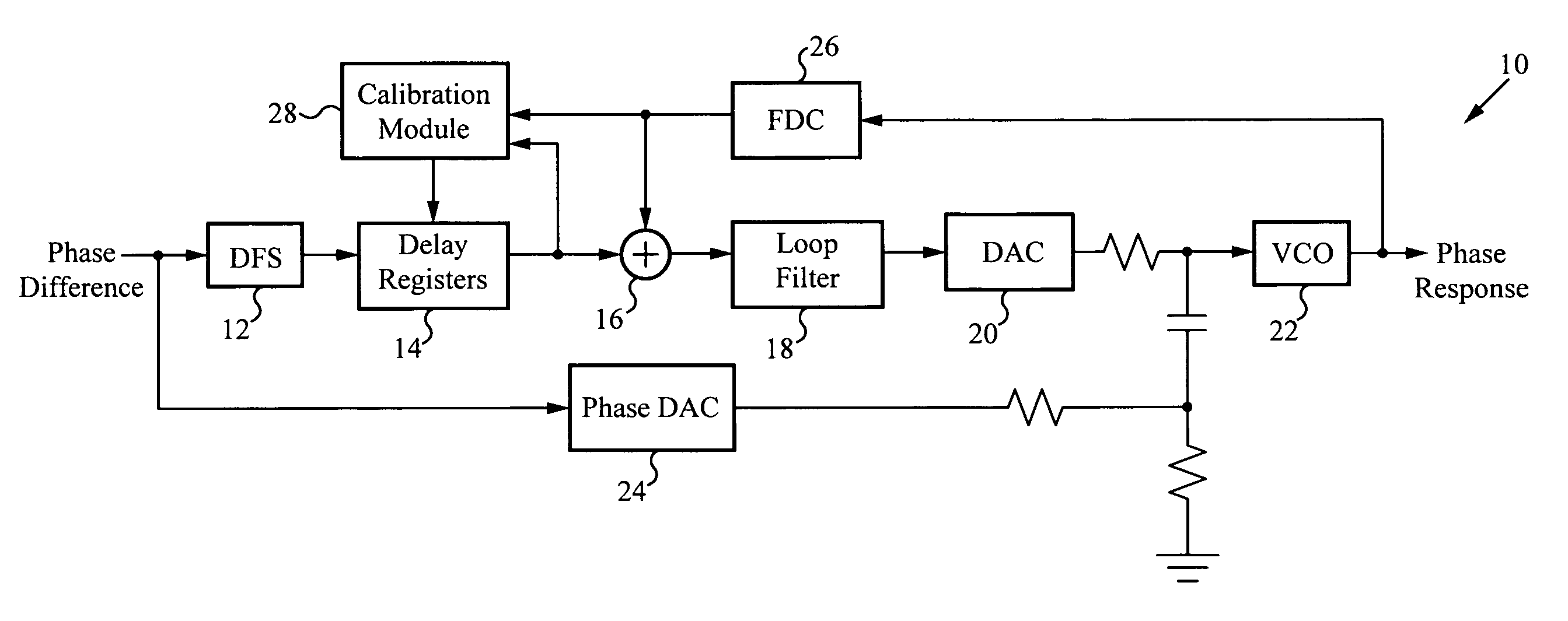
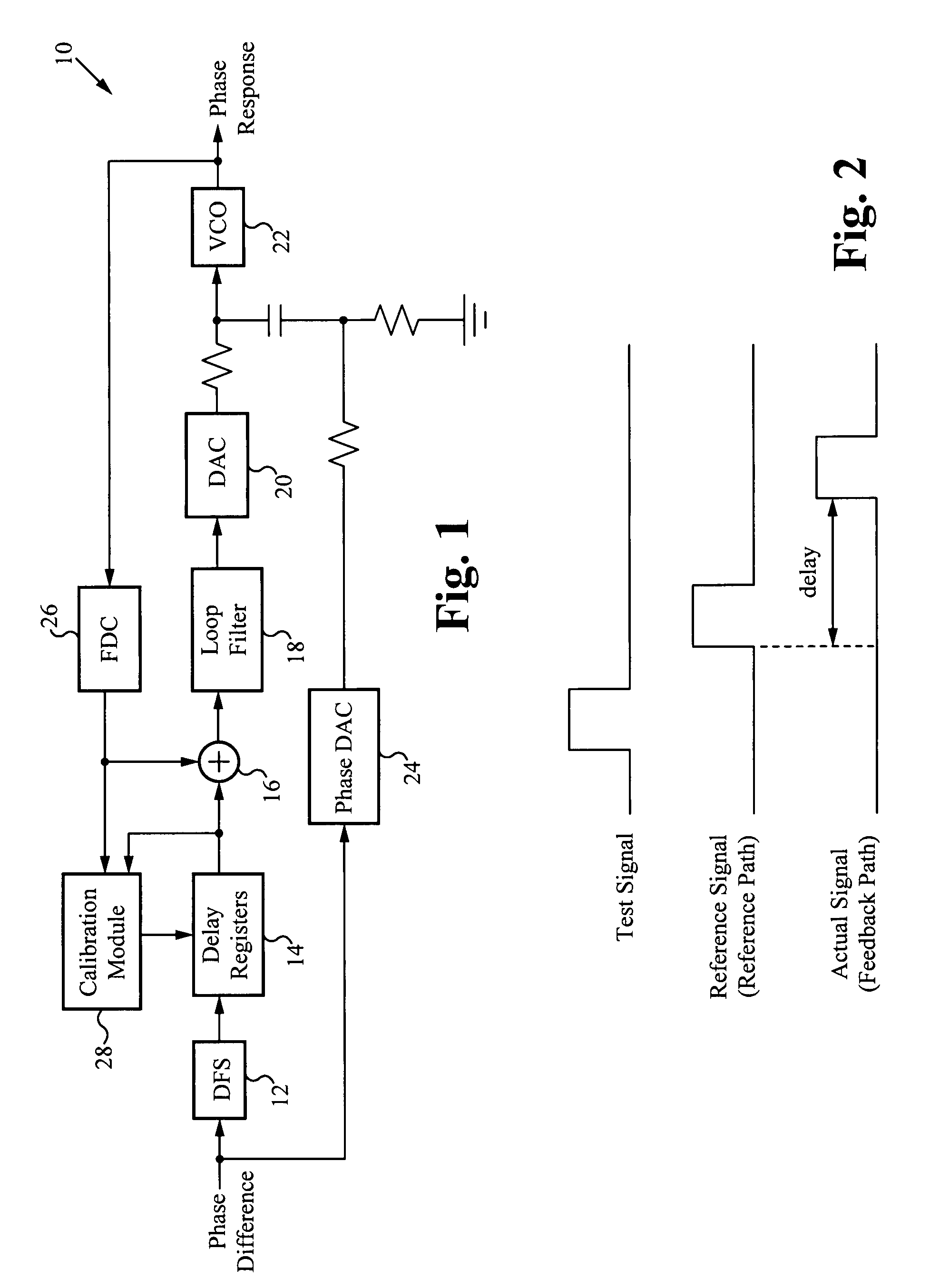
[0018]FIG. 1 illustrates an exemplary block diagram of a calibration circuit. In some embodiments, the calibration circuit is used for radio frequency (RF) applications, in which case the calibration circuit is a RF calibration circuit. The calibration circuit 10 includes a digital frequency synthesizer (DFS) 12, one or more delay registers 14, a comparator 16, a loop filter 18, a digital-to-analog converter (DAC) 20, a voltage controlled oscillator (VCO) 22, a phase digital-to-analog converter (DAC) 24, a frequency-to-digital converter (FDC) 26, and a calibration module 28. In some embodiments, the DAC 20 is a sigma-delta DAC, the phase DAC 24 is a 10-bit phase DAC, and the FDC 26 is a sigma-delta FDC. The calibration circuit 10 is configured as part of a phase modulation path. The calibration circuit 10 is configured to compensate for component timing delays that occur within the phase modulation. The output of the calibration circuit 10 is a phase response of the phase modulation...
second embodiment
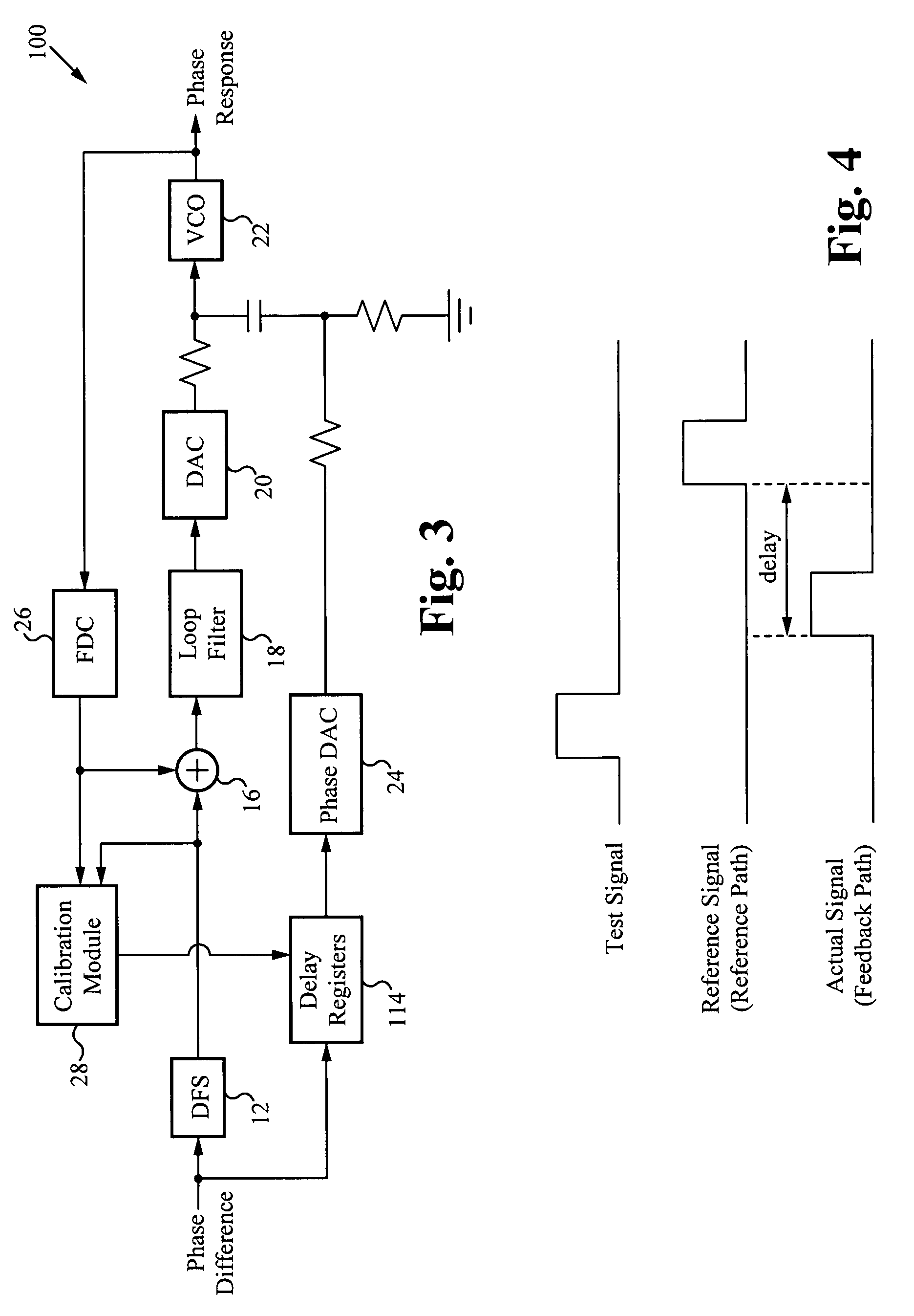
[0026]FIG. 3 illustrates an exemplary block diagram of a calibration circuit in which a timing delay is applied within a feedback path. The calibration circuit 100 functions similarly to the calibration circuit 10 of FIG. 1, with the exception that the delay registers are not configured within the reference path, as in the calibration circuit 10, but instead the delay registers 114 are configured within the feedback path of the calibration circuit 100. In this configuration, the actual signal received by the calibration circuit 100 is input to both the DFS 12 and the delay registers 114. The output of the delay registers 114 are input to the phase DAC 24. In the calibration circuit 100 shown in FIG. 3, the feedback path is configured such that the delay registers 114 are coupled to the input of the phase DAC 24. Alternatively, the delay registers 114 can be positioned anywhere within the feedback path.
[0027]FIG. 4 illustrates an exemplary timing diagram corresponding to the calibrat...
third embodiment
[0029]In general, it may not be pre-established which path, either the reference path or the feedback path, is the slower path. To account for either condition, a calibration circuit is configured with delay registers in both the reference path and the feedback path. Such a configuration enables the timing delay to be applied to either path, depending on which path is faster. FIG. 5 illustrates an exemplary block diagram of a calibration circuit 200 in which a timing delay is applied within a feedback path and a reference path. The calibration circuit 200 combines the configurations of the calibration circuit 10 (FIG. 1) and the calibration circuit 100 (FIG. 3), where the delay registers 14 are included in the reference path and the delay registers 114 are included in the feedback path. The calibration module 28 determines the timing delay as described above. If the actual signal from the feedback path is time delayed relative to the reference signal from the reference path, then th...
PUM
 Abstract
Description
Claims
Application Information
 - R&D
- Intellectual Property
- Life Sciences
- Materials
- Tech Scout
- Unparalleled Data Quality
- Higher Quality Content
- 60% Fewer Hallucinations
Browse by: Latest US Patents, China's latest patents, Technical Efficacy Thesaurus, Application Domain, Technology Topic, Popular Technical Reports.
© 2025 PatSnap. All rights reserved.Legal|Privacy policy|Modern Slavery Act Transparency Statement|Sitemap|About US| Contact US: help@patsnap.com